
13.3
TE and TM Standing Waves Between Parallel Plates
In this section, we delve into the relationship between the two-dimensional higher-order modes derived in Sec. 13.2 and their sources. The examples are chosen to relate directly to case studies treated in quasistatic terms in Chaps. 5 and 8.
The matching of a longitudinal boundary condition by a superposition of modes may at first seem to be a purely mathematical process. However, even qualitatively it is helpful to think of the influence of an excitation in terms of the resulting modes. For quasistatic systems, this has already been our experience. For the purpose of estimating the dependence of the output signal on the spacing b between excitation and detection electrodes, the EQS response of the capacitive attenuator of Sec. 5.5 could be pictured in terms of the lowest-order mode. In the electrodynamic situations of interest here, it is even more common that one mode dominates. Above its cutoff frequency, a given mode can propagate through a waveguide to regions far removed from the excitation.
Modes obey orthogonality relations that are mathematically useful for the evaluation of the mode amplitudes. Formally, the mode orthogonality is implied by the differential equations governing the transverse dependence of the fundamental field components and the associated boundary conditions. For the TM modes, these are (13.2.5) and (13.2.11).
TM Modes:
where
and for the TE modes, these are (13.2.8) and (13.2.12).
TE Modes:
where
The word "orthogonal" is used here to mean that
These properties of the modes can be seen simply by carrying out the integrals, using the modes as given by (13.2.13) and (13.2.16). More fundamentally, they can be deduced from the differential equations and boundary conditions themselves, (1) and (2). This was illustrated in Sec. 5.5 using arguments that are directly applicable here [(5.5.20)-(5.5.26)].
The following two examples illustrate how TE and TM modes can be excited in waveguides. In the quasistatic limit, the configurations respectively become identical to EQS and MQS situations treated in Chaps. 5 and 8.
Example 13.3.1. Excitation of TM Modes and the EQS Limit
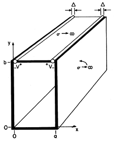
In the configuration shown in Fig. 13.3.1, the parallel plates lying in the planes x = 0 and x = a are shorted at y = 0 by a perfectly conducting plate. The excitation is provided by distributed voltage sources driving a perfectly conducting plate in the plane y = b. These sources constrain the integral of E across narrow insulating gaps of length
between the respective edges of the upper plate and the adjacent plates. All the conductors are modeled as perfect. The distributed voltage sources maintain the two-dimensional character of the fields even as the width in the z direction becomes long compared to a wavelength. Note that the configuration is identical to that treated in Sec. 5.5. Therefore, we already know the field behavior in the quasistatic (low frequency) limit.
Figure 13.3.1 Configuration for excitation of TM waves. In general, the two-dimensional fields are the sum of the TM and TE fields. However, here the boundary conditions can be met by the TM fields alone. Thus, we begin with Hz, (13.2.19), expressed as a single sum.
This field and the associated E satisfy the boundary conditions on the parallel plates at x = 0 and x = a. Boundary conditions are imposed on the tangential E at the longitudinal boundaries, where y = 0
and at the driving electrode, where y = b. We assume here that the gap lengths
are small compared to other dimensions of interest. Then, the electric field within each gap is conservative and the line integral of Ex across the gaps is equal to the gap voltages
v. Over the region between x =
and x = a -
, the perfectly conducting electrode makes Ex = 0.
Because the longitudinal boundary conditions are on Ex, we substitute Hz as given by (5) into the x component of Faraday's law [(12.6.6) of Table 12.8.3] to obtain
To satisfy the condition at the short, (6), An+ = An- and (8) becomes
This set of solutions satisfies the boundary conditions on three of the four boundaries. What we now do to satisfy the "last" boundary condition differs little from what was done in Sec. 5.5. The An+'s are adjusted so that the summation of product solutions in (9) matches the boundary condition at y = b summarized by (7). Thus, we write (9) with y = b on the right and with the function representing (7) on the left. This expression is multiplied by the m'th eigenfunction, cos (m
x/a), and integrated from x = 0 to x = a.
Because the intervals where
x(x, b) is finite are so small, the cosine function can be approximated by a constant, namely
1 as appropriate. On the right-hand side of (10), we exploit the orthogonality condition so as to pick out only one term in the infinite series.
Of the infinite number of terms in the integral on the right in (10), only the term where n = m has contributed. The coefficients follow from solving (11) and replacing m
n.
With the coefficients An+ = An- now determined, we can evaluate all of the fields. Substitution into (5), and (8) and into the result using (12.6.7) from Table 12.8.3 gives
Note the following aspects of these fields (which we can expect to see in Demonstration 13.3.1). First, the magnetic field is directed perpendicular to the x-y plane. Second, by making the excitation symmetric, we have eliminated the TEM mode. As a result, the only modes are of order n = 1 and higher. Third, at frequencies below the cutoff for the TM1 mode,
y is imaginary and the fields decay in the y direction.
6 sin (ju) = j sinh (u) and cos (ju) = cosh (u)
Indeed, in the quasistatic limit where
2

(
/a)2, the electric field is the same as that given by taking the gradient of (5.5.9). In this same quasistatic limit, the magnetic field would be obtained by using this quasistatic E to evaluate the displacement current and then solving for the resulting magnetic field subject to the boundary condition that there be no normal flux density on the surfaces of the perfect conductors. Fourth, above the cutoff frequency for the n = 1 mode but below the cutoff for the n = 2 mode, we should find standing waves having a wavelength 2
/
1.
Finally, note that each of the expressions for the field components has sin (
n b) in its denominator. With the frequency adjusted such that
n = n
/b, this function goes to zero and the fields become infinite. This resonance condition results in an infinite response, because we have pictured all of the conductors as perfect. It occurs when the frequency is adjusted so that a wave reflected from one boundary arrives at the other with just the right phase to reinforce, upon a second reflection, the wave currently being initiated by the drive.
The following experiment gives the opportunity to probe the fields that have been found in the previous example. In practical terms, the structure considered might be a parallel plate waveguide.
Demonstration 13.3.1. Evanescent and Standing TM Waves
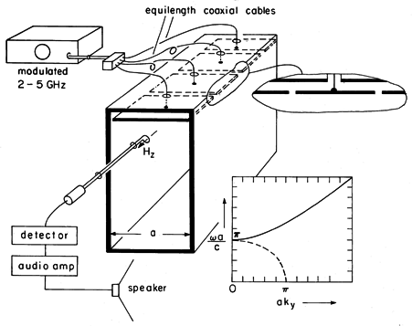
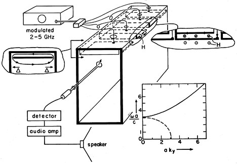
The experiment shown in Fig. 13.3.2 is designed so that the field distributions can be probed as the excitation is varied from below to above the cutoff frequency of the TM1 mode. The excitation structures are designed to give fields approximating those found in Example 13.3.1. For convenience, a = 4.8 cm so that the excitation frequency ranges above and below a cut-off frequency of 3.1 GHz. The generator is modulated at an audible frequency so that the amplitude of the detected signal is converted to "loudness" of the tone from the loudspeaker.
Figure 13.3.2 Demonstration of TM evanescent and standing waves. In this TM case, the driving electrode is broken into segments, each insulated from the parallel plates forming the waveguide and each attached at its center to a coaxial line from the generator. The segments insure that the fields applied to each part of the electrode are essentially in phase. (The cables feeding each segment are of the same length so that signals arrive at each segment in phase.) The width of the structure in the z direction is of the order of a wavelength or more to make the fields two dimensional. (Remember, in the vicinity of the lowest cutoff frequency, a is about one-half wavelength.) Thus, if the feeder were attached to a contiguous electrode at one point, there would be a tendency for standing waves to appear on the excitation electrode, much as they did on the wire antennae in Sec. 12.4. In the experiment, the segments are about a quarter-wavelength in the z direction but, of course, about a half-wavelength in the x direction.
In the experiment, H is detected by means of a one-turn coil. The voltage induced at the terminals of this loop is proportional to the magnetic flux perpendicular to the loop. Thus, for the TM fields, the loop detects its greatest signal when it is placed in an x - y plane. To avoid interference with E, the coaxial line connected to the probe as well as the loop itself are kept adjacent to the conducting walls (where Hz peaks anyway).
The spatial features of the field, implied by the normalized
versus ky plot of Fig. 13.3.2, can be seen by moving the probe about. With the frequency below cutoff, the field decays in the -y direction. This exponential decay or evanescence decreases to a linear dependence at cutoff and is replaced above cutoff by standing waves. The value of ky at a given frequency can be deduced from the experiment by measuring the quarter-wave distance from the short to the first null in the magnetic field. Note that if there are asymmetries in the excitation that result in excitation of the TEM mode, the standing waves produced by this mode will tend to obscure the TM1 mode when it is evanescent. The TEM waves do not have a cutoff!
As we have seen once again, the TM fields are the electrodynamic generalization of two-dimensional EQS fields. That is, in the quasistatic limit, the previous example becomes the capacitive attenuator of Sec. 5.5.7
7The example which was the theme of Sec. 5.5 might equally well have been called the "microwave attenuator," for a section of waveguide operated below cutoff is used in microwave circuits to attenuate signals.
We have more than one reason to expect that the two-dimensional TE fields are the generalization of MQS systems. First, this was seen to be the case in Sec. 12.6, where the TE fields associated with a given surface current density were found to approach the MQS limit as2

ky2. Second, from Sec. 8.6 we know that for every two-dimensional EQS configuration involving perfectly conducting boundaries, there is an MQS one as well.
8 The H satisfying the condition that nB = 0 on the perfectly conducting boundaries was obtained by replacing

Az in the solution to the analogous EQS problem.
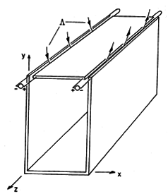
In particular, the MQS analog of the capacitor attenuator is the configuration shown in Fig. 13.3.3. The MQS H field was found in Example 8.6.3.
In treating MQS fields in the presence of perfect conductors, we recognized that the condition of zero tangential E implied that there be no time-varying normal B. This made it possible to determine H without regard for E. We could then delay taking detailed account of E until Sec. 10.1. Thus, in the MQS limit, a system involving essentially a two-dimensional distribution of H can (and usually does) have an E that depends on the third dimension. For example, in the configuration of Fig. 13.3.3, a voltage source might be used to drive the current in the z direction through the upper electrode. This current is returned in the perfectly conducting
-shaped walls. The electric fields in the vicinities of the gaps must therefore increase in the z direction from zero at the shorts to values consistent with the voltage sources at the near end. Over most of the length of the system, E is across the gap and therefore in planes perpendicular to the z axis. This MQS configuration does not excite pure TE fields. In order to produce (approximately) two-dimensional TE fields, provision must be made to make E as well as H two dimensional. The following example and demonstration give the opportunity to further develop an appreciation for TE fields.
Figure 13.3.3 Two-dimensional MQS configuration that does not have TE fields.
Example 13.3.2. Excitation of TE Modes and the MQS Limit
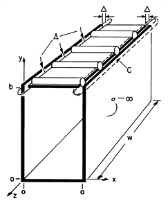
An idealized configuration for exciting standing TE modes is shown in Fig. 13.3.4. As in Example 13.3.1, the perfectly conducting plates are shorted in the plane y = 0. In the plane y = b is a perfectly conducting plate that is segmented in the z direction. Each segment is driven by a voltage source that is itself distributed in the x direction. In the limit where there are many of these voltage sources and perfectly conducting segments, the driving electrode becomes one that both imposes a z-directed E and has no z component of B. That is, just below the surface of this electrode, w Ez is equal to the sum of the source voltages. One way of approximately realizing this idealization is used in the next demonstration.
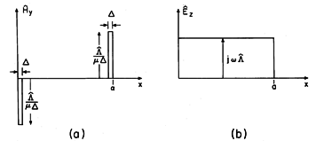
Figure 13.3.4 Idealized configuration for excitation of TE standing waves. Let
be defined as the flux per unit length (length taken along the z direction) into and out of the enclosed region through the gaps of width
between the driving electrode and the adjacent edges of the plane parallel electrodes. The magnetic field normal to the driving electrode between the gaps is zero. Thus, at the upper surface, Hy has the distribution shown in Fig. 13.3.5a.
Figure 13.3.5 Equivalent boundary conditions on normal H and tangential E at y = b. Faraday's integral law applied to the contour C of Fig. 13.3.4 and to a similar contour around the other gap shows that
Thus, either the normal B or the tangential E on the surface at y = b is specified. The two must be consistent with each other, i.e., they must obey Faraday's law. It is perhaps easiest in this case to deal directly with Ez in finding the coefficients appearing in (13.2.20). Once they have been determined (much as in Example 13.3.1), H follows from Faraday's law, (12.6.29) and (12.6.30) of Table 12.8.3.
In the quasistatic limit,
2

(m
/a)2, this magnetic field reduces to that found in Example 8.6.3.
A few observations may help one to gain some insights from these expressions. First, if the magnetic field is sensed, then the detection loop must have its axis in the x - y plane. For these TE modes, there should be no signal sensed with the axis of the detection loop in the z direction. This probe can also be used to verify that H normal to the perfectly conducting surfaces is indeed zero, while its tangential value peaks at the short. Second, the same decay of the fields below cutoff and appearance of standing waves above cutoff is predicted here, as in the TM case. Third, because E is perpendicular to planes of constant z, the boundary conditions on E, and hence H, are met, even if perfectly conducting plates are placed over the open ends of the guide, say in the planes z = 0 and z = w. In this case, the guide becomes a closed pipe of rectangular cross-section. What we have found are then a subset of the three-dimensional modes of propagation in a rectangular waveguide.
Demonstration 13.3.2. Evanescent and Standing TE Waves
The apparatus of Demonstration 13.3.1 is altered to give TE rather than TM waves by using an array of "one-turn inductors" rather than the array of "capacitor plates." These are shown in Fig. 13.3.6.
Figure 13.3.6 Demonstration of evanescent and standing TE waves. Each member of the array consists of an electrode of width a - 2
, driven at one edge by a common source and shorted to the perfectly conducting backing at its other edge. Thus, the magnetic flux through the closed loop passes into and out of the guide through the gaps of width
between the ends of the one-turn coil and the parallel plate (vertical) walls of the guide. Effectively, the integral of Ez created by the voltage sources in the idealized model of Fig. 13.3.4 is produced by the integral of Ez between the left edge of one current loop and the right edge of the next.
The current loop can be held in the x - z plane to sense Hy or in the y - z plane to sense Hx to verify the field distributions derived in the previous example. It can also be observed that placing conducting sheets against the open ends of the parallel plate guide, making it a rectangular pipe guide, leaves the characteristics of these two-dimensional TE modes unchanged.


