The superposition principle is now used to find the solution of
Poisson's equation for any given charge distribution  (r ).
The argument presented in the previous section for singular charge
distributions suggests the approach.
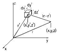
For the purpose of representing the arbitrary charge density distribution as a sum of "elementary" charge distributions, we subdivide the space occupied by the charge density into elementary volumes of size dx'dy'dz'. Each of these elements is denoted by the Cartesian coordinates (x',y',z'), as shown in Fig. 4.5.1. The charge contained in one of these elementary volumes, the one with the coordinates (x',y',z'), is

We now express the total potential due to the charge density  as
the superposition of the potentials d
 due to the differential
elements of charge, (1), positioned at the points r'. Note that
each of these elementary charge distributions has zero charge density
at all points outside of the volume element dv' situated at
r'. Thus, they represent point charges of magnitudes dq
given by (1). Provided that |r - r'| is taken as the
distance between the point of observation r and the position of
one incremental charge r', the potential associated with this
incremental charge is given by (4.4.1).

where in Cartesian coordinates

Note that (2) is a function of two sets of Cartesian coordinates: the (observer) coordinates (x,y,z) of the point r at which the potential is evaluated and the (source) coordinates (x',y',z') of the point r' at which the incremental charge is positioned.
According to the superposition principle, we obtain the total potential produced by the sum of the differential charges by adding over all differential potentials, keeping the observation point (x,y,z) fixed. The sum over the differential volume elements becomes a volume integral over the coordinates (x' , y' , z' ).

This is the superposition integral for the electroquasistatic potential.
The evaluation of the potential requires that a triple integration be carried out. With the help of a computer, or even a programmable calculator, this is a straightforward process. There are few examples where the three successive integrations are carried out analytically without considerable difficulty.
There are special representations of (3), appropriate in cases where the charge distribution is confined to surfaces, lines, or where the distribution is two dimensional. For these, the number of integrations is reduced to two or even one, and the difficulties in obtaining analytical expressions are greatly reduced.
Three-dimensional charge distributions can be represented as the superposition of lines and sheets of charge and, by exploiting the potentials found analytically for these distributions, the numerical integration that might be required to determine the potential for a three-dimensional charge distribution can be reduced to two or even one numerical integration.
Superposition Integral for Surface Charge Density
If the charge density is confined to regions that can be described
by surfaces having a very small thickness  , then one of the three
integrations of (3) can be carried out in general. The situation is
as pictured in Fig. 4.5.2, where the distance to the observation
point is large compared to the thickness over which the charge is
distributed. As the integration of (3) is carried out over this
thickness
  , the distance between source and observer, |r -
r'|, varies little. Thus, with
  used to denote a
coordinate that is locally perpendicular to the surface, the general
superposition integral, (3), reduces to

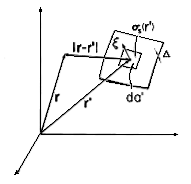
The integral on  is by definition the surface charge density. Thus,
(4) becomes a form of the superposition integral applicable where
the charge distribution can be modeled as being on a surface.

The following example illustrates the application of this integral.
Example 4.5.1. Potential of a Uniformly Charged Disk
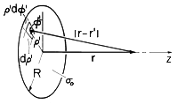
The disk shown in Fig. 4.5.3 has a radius R and carries a uniform surface charge density
o. The following steps lead to the potential and field on the axis of the disk.
Figure 4.5.3 A uniformly charged disk with coordinates for finding the potential along the z axis. The distance |r - r'| between the point r' at radius
and angle
(in cylindrical coordinates) and the point r on the axis of the disk (the z axis) is given by
It follows that (5) is expressible in terms of the following double integral
where we have allowed for both positive z, the case illustrated in the figure, and negative z. Note that these are points on opposite sides of the disk.
The axial field intensity Ez can be found by taking the gradient of (7) in the z direction.
The upper sign applies to positive z, the lower sign to negative z.
The potential distribution of (8) can be checked in two limiting cases for which answers are easily obtained by inspection: the potential at a distance |z|
R, and the field at |z| \ll R.
observation from the disk, the radius of the disk R is small compared to |z|, and the potential of the disk must approach the potential of a point charge of magnitude equal to the total charge of the disk,
o
R2. The potential given by (7) can be expanded in powers of R/z
to find that
indeed approaches the potential function
of a point charge at distance |z| from the observation point.
(a) At a very large distance |z| of the point of (b) At |z| R, on either side of the disk, the field of the disk must approach that of a charge sheet of very large (infinite) extent. But that field is

o /2
o. We find, indeed, that in the limit |z|
0, (8) yields this limiting result.
Superposition Integral for Line Charge Density
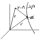
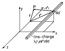
Another special case of the general superposition integral, (3), pertains to fields from charge distributions that are confined to the neighborhoods of lines. In practice, dimensions of interest are large compared to the cross-sectional dimensions of the area A' of the charge distribution. In that case, the situation is as depicted in Fig. 4.5.4, and in the integration over the cross-section the distance from source to observer is essentially constant. Thus, the superposition integral, (3), becomes
Figure 4.5.4 An element of line charge at the position r' gives rise to a potential at the observer location r. In view of the definition of the line charge density, (1.3.10), this expression becomes
Example 4.5.2. Field of Collinear Line Charges of Opposite Polarity
A positive line charge density of magnitude
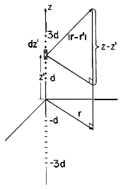
o is uniformly distributed along the z axis between the points z = d and z = 3d. Negative charge of the same magnitude is distributed between z = -d and z = -3d. The axial symmetry suggests the use of the cylindrical coordinates defined in Fig. 4.5.5.
Figure 4.5.5 Collinear positive and negative line elements of charge symmetrically located on the z axis. The distance from an element of charge
o dz' to an arbitrary observer point (r, z) is
Thus, the line charge form of the superposition integral, (12), becomes
These integrations are carried out to obtain the desired potential distribution
Here, lengths have been normalized to d, so that z = z/d and r = r/d. Also, the potential has been normalized such that
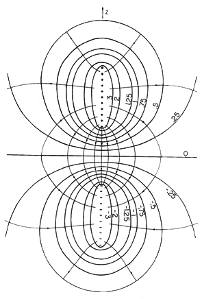
Figure 4.5.6 Cross-section of equipotential surfaces and lines of electric field intensity for the configuration of Fig. 4.5.5 A programmable calculator can be used to evaluate (15), given values of (r, z). The equipotentials in Fig. 4.5.6 were, in fact, obtained in this way, making it possible to sketch the lines of field intensity shown. Remember, the configuration is axisymmetric, so the equipotentials are surfaces generated by rotating the cross-section shown about the z axis.
Two-Dimensional Charge and Field Distributions
In two-dimensional configurations, where the charge distribution uniformly extends from z = -
to z = +
, one of the three integrations of the general superposition integral is carried out by representing the charge by a superposition of line charges, each extending from z = -
to z = +
. The fundamental element of charge, shown in Fig. 4.5.7, is not the point charge of (1) but rather an infinitely long line charge. The associated potential is not that of a point charge but rather of a line charge.
Figure 4.5.7 For two-dimensional charge distributions, the elementary charge takes the form of a line charge of infinite length. The observer and source position vectors, r and r', are two-dimensional vectors. With the line charge distributed along the z axis, the electric field is given by (1.3.13) as
and integration of this expression gives the potential
where ro is a reference radius brought in as a constant of integration. Thus, with da denoting an area element in the plane upon which the source and field depend and r and r' the vector positions of the observer and source respectively in that plane, the potential for the incremental line charge of Fig. 4.5.7 is written by making the identifications
Integration over the given two-dimensional source distribution then gives as the two-dimensional superposition integral
In dealing with charge distributions that extend to infinity in the z direction, the potential at infinity can not be taken as a reference. The potential at an arbitrary finite position can be defined as zero by adding an integration constant to (20).
The following example leads to a result that will be found useful in solving boundary value problems in Sec. 4.8.
Example 4.5.3. Two-Dimensional Potential of Uniformly Charged Sheet
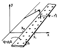
A uniformly charged strip lying in the y = 0 plane between x = x2 and x = x1 extends from z = +
to z = -
, as shown in Fig. 4.5.8. Because the thickness of the sheet in the y direction is very small compared to other dimensions of interest, the integrand of (20) is essentially constant as the integration is carried out in the y direction. Thus, the y integration amounts to a multiplication by the thickness
of the sheet
Figure 4.5.8 Strip of uniformly charged material stretches to infinity in the z directions, giving rise to two-dimensional potential distribution.
and (20) is written in terms of the surface charge density
s as
If the distance between source and observer is written in terms of the Cartesian coordinates of Fig. 4.5.8, and it is recognized that the surface charge density is uniform so that
s =
o is a constant, (22) becomes
Introduction of the integration variable u = x - x' converts this integral to an expression that is readily integrated.
Two-dimensional distributions of surface charge can be piece-wise approximated by uniformly charged planar segments. The associated potentials are then represented by superpositions of the potential given by (24).
Potential of Uniform Dipole Layer
The potential produced by a dipole of charges
q spaced a vector distance d apart has been found to be given by (4.4.11)
where
A dipole layer, shown in Fig. 4.5.9, consists of a pair of surface charge distributions

s spaced a distance d apart. An area element da of such a layer, with the direction of da (pointing from the negative charge density to the positive one), can be regarded as a differential dipole producing a (differential) potential d

Denote the surface dipole density by
s where
and the potential produced by a surface dipole distribution over the surface S is given by
This potential can be interpreted particularly simply if the dipole density is constant. Then
s can be pulled out from under the integral, and there
is equal to
s /(4
o ) times the integral
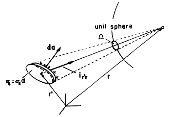
This integral is dimensionless and has a simple geometric interpretation. As shown in Fig. 4.5.9, ir' r
da is the area element projected into the direction connecting the source point to the point of observation. Division by |r - r'|2 reduces this projected area element onto the unit sphere. Thus, the integrand is the differential solid angle subtended by da as seen by an observer at r. The integral, (29), is equal to the solid angle subtended by the surface S when viewed from the point of observation r. In terms of this solid angle,
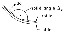
Figure 4.5.9 The differential solid angle subtended by dipole layer of area da. Next consider the discontinuity of potential in passing through the surface S containing the dipole layer. Suppose that the surface S is approached from the + side; then, from Fig. 4.5.10, the surface is viewed under the solid angle \Omegao. Approached from the other side, the surface subtends the solid angle -(4
- \Omegao). Thus, there is a discontinuity of potential across the surface of
Because the dipole layer contains an infinite surface charge density
s, the field within the layer is infinite. The "fringing" field, i.e., the external field of the dipole layer, is finite and hence negligible in the evaluation of the internal field of the dipole layer. Thus, the internal field follows directly from Gauss' law under the assumption that the field exists solely between the two layers of opposite charge density (see Prob. 4.5.12). Because contributions to (28) are dominated by
s in the immediate vicinity of a point r as it approaches the surface, the discontinuity of potential is given by (31) even if
s is a function of position. In this case, the tangential E is not continuous across the interface (Prob. 4.5.12).
Figure 4.5.10 The solid angle from opposite sides of dipole layer.


