In most electroquasistatic situations, the surfaces of metals are equipotentials. In fact, if surrounded by insulators, the surfaces of many other conducting materials also tend to form equipotential surfaces. The electrical properties and dynamical conditions required for representing a boundary surface of a material by an equipotential will be identified in Chap. 7.
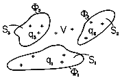
Consider the situation shown in Fig. 4.6.l, where three surfaces Si,
i = 1, 2, 3 are held at the potentials  1,
1,  2, and
 3, respectively. These
are presumably the surfaces of conducting electrodes. The field in
the volume V surrounding the surfaces Si and extending to infinity is
not only due to the charge in that volume but due to charges outside
that region as well. Fields normal to the boundaries terminate on
surface charges. Thus, as far as the fields in the region of
interest are concerned, the sources are the charge density in the
volume V (if any) and the surface charges on the surrounding
electrodes.
The superposition integral, which is a solution to Poisson's
equation, gives the potential when the volume and surface charges are
known. In the present statement of the problem, the volume charge
densities are known in V, but the surface charge densities are not.
The only fact known about the latter is that they must be so
distributed as to make the Si's into equipotential surfaces at the
potentials  i.
i.
The determination of the charge distribution for the set of
specified equipotential surfaces is not a simple matter and will
occupy us in Chap. 5. But many interesting physical situations are
uncovered by a different approach. Suppose we are given a potential
function  (r ).
Then any equipotential surface of that potential can
be replaced by an electrode at the corresponding potential. Some of
the electrode configurations and associated fields obtained in this
manner are of great practical interest.
Suppose such a procedure has been followed. To determine the charge on the i-th electrode, it is necessary to integrate the surface charge density over the surface of the electrode.

In the volume V, the contributions of the surface charges on the equipotential surfaces are exactly equivalent to those of the charge distribution inside the regions enclosed by the surface Si causing the original potential function. Thus, an alternative to the use of (1) for finding the total charge on the electrode is

where Vi is the volume enclosed by the surface Si and
 is the charge density inside Si associated with the
original potential.
Capacitance
Suppose the system consists of only two electrodes, as shown in Fig. 4.6.2. The charges on the surfaces of conductors (1) and (2) can be evaluated from the assumedly known solution by using (1).
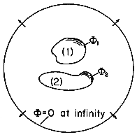

Further, there is a charge at infinity of

The charge at infinity is the negative of the sum of the charges on the two electrodes. This follows from the fact that the field is divergence free, and all field lines originating from q1 and q2 must terminate at infinity. Instead of the charges, one could specify the potentials of the two electrodes with respect to infinity. If the charge on electrode 1 is brought to it by a voltage source (battery) that takes charge away from electrode 2 and deposits it on electrode 1, the normal process of charging up two electrodes, then q1 = -q2. A capacitance C between the two electrodes can be defined as the ratio of charge on electrode 1 divided by the voltage between the two electrodes. In terms of the fields, this definition becomes

In order to relate this definition to the capacitance concept used in circuit theory, one further observation must be made. The capacitance relates the charge of one electrode to the voltage between the two electrodes. In general, there may also exist a voltage between electrode 1 and infinity. In this case, capacitances must also be assigned to relate the voltage with regard to infinity to the charges on the electrodes. If the electrodes are to behave as the single terminal-pair element of circuit theory, these capacitances must be negligible. Returning to (5), note that C is independent of the magnitude of the field variables. That is, if the magnitude of the charge distribution is doubled everywhere, it follows from the superposition integral that the potential doubles as well. Thus, the electric field in the numerator and denominator of (3) is doubled everywhere. Each of the integrals therefore also doubles, their ratio remaining constant.
Example 4.6.1. Capacitance of Isolated Spherical Electrodes
A spherical electrode having radius a has a well-defined capacitance C relative to an electrode at infinity. To determine C, note that the equipotentials of a point charge q at the origin
are spherical. In fact, the equipotential having radius r = a has a voltage with respect to infinity of
The capacitance is defined as the the net charge on the surface of the electrode per unit voltage, (5). But the net charge found by integrating the surface charge density over the surface of the sphere is simply q, and so the capacitance follows from (7) as
By way of illustrating the conditions necessary for the capacitance to be well defined, consider a pair of spherical electrodes. Electrode (1) has radius a while electrode (2) has radius R. If these are separated by many times the larger of these radii, the potentials in their vicinities will again take the form of (6). Thus, with the voltages v1 and v2 defined relative to infinity, the charges on the respective spheres are
With all of the charge on sphere (1) taken from sphere (2),
Under this condition, all of the field lines from sphere (1) terminate on sphere (2). To determine the capacitance of the electrode pair, it is necessary to relate the charge q1 to the voltage difference between the spheres. To this end, (9) is used to write
and because q1 = -q2, it follows that
where C is now the capacitance of one sphere relative to the other.
Note that in order to maintain no net charge on the two spheres, it follows from (9), (10), and (12) that the average of the voltages relative to infinity must be retained at
Thus, the average potential must be raised in proportion to the potential difference v.
Example 4.6.2. Field and Capacitance of Shaped Electrodes
The field due to oppositely charged collinear line charges was found to be (4.5.15) in Example 4.5.2. The equipotential surfaces, shown in cross-section in Fig. 4.5.6, are melon shaped and tend to enclose one or the other of the line charge elements.
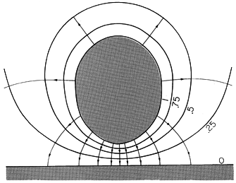
Suppose that the surfaces on which the normalized potentials are equal to 1 and to 0, respectively, are turned into electrodes, as shown in Fig. 4.6.3. Now the field lines originate on positive surface charges on the upper electrode and terminate on negative charges on the ground plane. By contrast with the original field from the line charges, the field in the region now inside the electrodes is zero.
Figure 4.6. The \un = 1 and \un
= 0 equipotentials of Fig. 4.5.6 are turned into perfectly conducting electrodes having the capacitance of (4.6.16).
One way to determine the net charge on one of the electrodes requires that the electric field be found by taking the gradient of the potential, that the unit normal vector to the surface of the electrode be determined, and hence that the surface charge be determined by evaluating
o E
da on the electrode surface. Integration of this quantity over the electrode surface then gives the net charge. A far easier way to determine this net charge is to recognize that it is the same as the net charge enclosed by this surface for the original line charge configuration. Thus, the net charge is simply 2d
l, and if the potentials of the respective electrodes are taken as
V, the capacitance is
For the surface of the electrode in Fig. 4.6.3,
It follows from these relations that the desired capacitance is simply
In these two examples, the charge density is zero everywhere between the electrodes. Thus, throughout the region of interest, Poisson's equation reduces to Laplace's equation.
The solution to Poisson's equation throughout all space is tantamount to solving Laplace's equation in a limited region, subject to certain boundary conditions. A more direct approach to finding such solutions is taken in the next chapter. Even then, it is well to keep in mind that solutions to Laplace's equation in a limited region are solutions to Poisson's equation throughout the entire space, including those regions that contain the charges.
The next example leads to an often-used result, the capacitance per unit length of a two-wire transmission line.
Example 4.6.3. Potential of Two Oppositely Charged Conducting Cylinders
The potential distribution between two equal and opposite parallel line charges has circular cylinders for its equipotential surfaces. Any pair of these cylinders can be replaced by perfectly conducting surfaces so as to obtain the solution to the potential set up between two perfectly conducting parallel cylinders of circular cross-section.
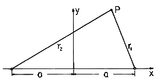
Figure 4.6.4 Definition of coordinates for finding field from line charges of opposite sign at x = a. The displacement vectors are two dimensional and hence in the x-y plane.
We proceed in the following ways: (a) The potentials produced by two oppositely charged parallel lines positioned at x = +a and x = -a, respectively, as shown in Fig. 4.6.4, are superimposed. (b) The intersections of the equipotential surfaces with the x - y plane are circles. The above results are used to find the potential distribution produced by two parallel circular cylinders of radius R with their centers spaced by a distance 2l. (c) The cylinders carry a charge per unit length
l and have a potential difference V, and so their capacitance per unit length is determined.
(a) The potential associated with a single line charge on the z axis is most easily obtained by integrating the electric field, (1.3.13), found from Gauss' integral law. It follows by superposition that the potential for two parallel line charges of charge per unit length +
l and -
l, positioned at x = +a and x = -a, respectively, is
Here r1 and r2 are the distances of the field point P from the + and - line charges, respectively, as shown in Fig. 4.6.4.
(b) On an equipotential surface,
= U is a constant and the equation for that surface, (18), is
where in Cartesian coordinates
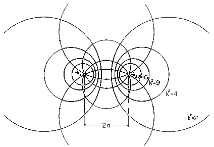
With the help of Fig. 4.6.4, (19) is seen to represent cylinders of circular cross-section with centers on the x axis. This becomes apparent when the equation is expressed in Cartesian coordinates. The equipotential circles are shown in Fig. 4.6.5 for different values of
Figure 4.6.5 Cross-section of equipotentials and electric field lines for line charges.
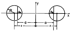
(c) Given two conducting cylinders whose centers are a distance 2l apart, as shown in Fig. 4.6.6, what is the location of the two line charges such that their field has equipotentials coincident with these two cylinders? In terms of k as defined by (20), (19) becomes
Figure 4.6.6 Cross-section of parallel circular cylinders with centers at x = l and line charges at x =
a, having equivalent field.
This expression can be written as a quadratic function of x and y.
Equation (22) confirms that the loci of constant potential in the x - y plane are indeed circles. In order to relate the radius and location of these circles to the parameters a and k, note that the expression for a circle having radius R and center on the x axis at x = l is
We can make (22) identical to this expression by setting
and
Given the spacing 2l and radius R of parallel conductors, this last expression can be used to locate the positions of the line charges. It also can be used to see that (l - a) = R2/(l + a), which can be used with (24) solved for k2 to deduce that
Introduction of this expression into (20) then relates the potential of the cylinder on the right to the line charge density. The net charge per unit length that is actually on the surface of the right conductor is equal to the line charge density
l. With the voltage difference between the cylinders defined as V = 2U, we can therefore solve for the capacitance per unit length.
Often, the cylinders are wires and it is appropriate to approximate this result for large ratios of l/R.
Thus, the capacitance per unit length is approximately
This same result can be obtained directly from (18) by recognizing that when a
l, the line charges are essentially at the center of the cylinders. Thus, evaluated on the surface of the right cylinder where the potential is V/2, r1 \simeq R and r2 \simeq 2l, (18) gives (29).
Example 4.6.4. Attraction of a Charged Particle to a Neutral Sphere
A charged particle facing a conducting sphere induces a surface charge distribution on the sphere. This distribution adjusts itself so as to make the spherical surface an equipotential. In this problem, we take advantage of the fact that two charges of opposite sign produce a potential distribution, one equipotential surface of which is a sphere.
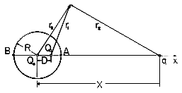
First we find the potential distribution set up by a perfectly conducting sphere of radius R, carrying a net charge Q, and a point charge q at a distance X (X
R) from the center of the sphere. Then the result is used to determine the force on the charge q exerted by a neutral sphere (Q = 0)! The configuration is shown in Fig. 4.6.7.
Figure 4.6.7 Cross-section of spherical electrode having radius R and center at the origin of x axis, showing charge q at x = X. Charge Q1 at x = D makes spherical surface an equipotential, while Qo at origin makes the net charge on the sphere zero without disturbing the equipotential condition. Consider first the potential distribution set up by a point charge Q1 and another point charge q. The construction of the potential is familiar from Sec. 4.4.
In general, the equipotentials are not spherical. However, the surface of zero potential
is described by
and if q/Q1
0, this represents a sphere. This can be proven by expressing (32) in Cartesian coordinates and noting that in the plane of the two charges, the result is the equation of a circle with its center on the axis intersecting the two charges [compare (19)].
Using this fact, we can apply (32) to the points A and B in Fig. 4.6.7 and eliminate q/Q1. Taking R as the radius of the sphere and D as the distance of the point charge Q1 from the center of the sphere, it follows that
This specifies the distance D of the point charge Q1 from the center of the equipotential sphere. Introduction of this result into (32) applied to point A gives the (fictitious) charge Q1.
With this value for Q1 located in accordance with (33), the surface of the sphere has zero potential. Without altering its equipotential character, the potential of the sphere can be shifted by positioning another fictitious charge at its center. If the net charge of the spherical conductor is to be Q, then a charge Qo = Q - Q1 is to be positioned at the center of the sphere. The net field retains the sphere as an equipotential surface, now of nonzero potential. The field outside the sphere is the sought-for solution. With r3 defined as the distance from the center of the sphere to the point of observation, the field outside the sphere is
With Q = 0, the force on the charge follows from an evaluation of the electric field intensity directed along an axis passing through the center of the sphere and the charge q. The self-field of the charge is omitted from this calculation. Thus, along the x axis the potential due to the fictitious charges within the sphere is
The x directed electric field intensity, and hence the required force, follows as
In view of (33) and (34), this can be written in terms of the actual physical quantities as
The field implied by (34) with Q = 0 is shown in Fig. 4.6.8. As the charge approaches the spherical conductor, images are induced on the nearest parts of the surface. To keep the net charge zero, charges of opposite sign must be induced on parts of the surface that are more remote from the point charge. The force of attraction results because the charges of opposite sign are closer to the point charge than those of the same sign.


