| | Polarization Density |
|---|
| 6.1.1 | The layer of polarized material shown in cross-section in Fig.
P6.1.1, having thickness d and surfaces in the planes y = d and y
= 0, has the polarization density P = Po cos  x(ix +
iy). x(ix +
iy).
 Figure P6.1.1
| (a) | Determine the polarization charge density throughout the slab.
|
| (b) | What is the surface polarization charge density on the
layer surfaces?
|
|
| | Laws and Continuity Conditions with Polarization |
|---|
| 6.2.1 | For the polarization density given in Prob. 6.1.1, with Po(t) = Po
cos  t: t:
| (a) | Determine the polarization current density and polarization charge density.
|
| (b) | Using Jp and  p, show that the differential charge
conservation law, (10), is indeed satisfied. p, show that the differential charge
conservation law, (10), is indeed satisfied.
|
|
| | Permanent Polarization |
|---|
| 6.3.1* | A layer of permanently polarized material is sandwiched between
plane parallel perfectly conducting electrodes in the planes x = 0 and
x = a, respectively, having potentials  = 0 and = 0 and  = -V.
The system extends to infinity in the = -V.
The system extends to infinity in the  y and y and  z directions. z directions.
| (a) | Given that P = Po cos  x ix, show that the potential between the electrodes is x ix, show that the potential between the electrodes is

|
| (b) | Given that P = Po cos  y iy, show that the
potential between the electrodes is y iy, show that the
potential between the electrodes is

|
|
| 6.3.2 | The cross-section of a configuration that extends to infinity in
the  z directions is shown in Fig. P6.3.2. What is the potential
distribution inside the cylinder of rectangular cross-section? z directions is shown in Fig. P6.3.2. What is the potential
distribution inside the cylinder of rectangular cross-section?
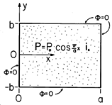 Figure P6.3.2
|
| 6.3.3* | A polarization density is given in the semi-infinite half-space
y < 0 to be P = Po cos [(2 / / )x]iy. There are
no other field sources in the system and Po and )x]iy. There are
no other field sources in the system and Po and  are given
constants. are given
constants.
| (a) | Show that  p = 0 and p = 0 and  sp = Po cos (2 sp = Po cos (2 x/ x/ ). ).
|
| (b) | Show that

|
|
| 6.3.4 | A layer in the region -a < y < 0 has the polarization density
P = Po iy sin  (x - xo). In the planes y = (x - xo). In the planes y =  a,
the potential is constrained to be a,
the potential is constrained to be  = V cos = V cos  x, where
Po, x, where
Po,  and V are given constants. The region 0 < y < a
is free space and the system extends to infinity in the and V are given constants. The region 0 < y < a
is free space and the system extends to infinity in the  x and x and
 z directions. Find the potential in regions (a) and (b) in the
free space and polarized regions, respectively. (If you have already
solved Prob. 5.6.12, you can solve this problem by inspection.) z directions. Find the potential in regions (a) and (b) in the
free space and polarized regions, respectively. (If you have already
solved Prob. 5.6.12, you can solve this problem by inspection.)
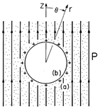 Figure P6.3.5
|
| 6.3.5* | Figure P6.3.5 shows a material having the uniform polarization
density P = Po iz, with a spherical cavity having radius R.
On the surface of the cavity is a uniform distribution of unpaired
charge having density  su = su =  o. The interior of the
cavity is free space, and Po and o. The interior of the
cavity is free space, and Po and  o are given constants.
The potential far from the cavity is zero. Show that the electric
potential is o are given constants.
The potential far from the cavity is zero. Show that the electric
potential is

|
| 6.3.6 | The cross-section of a groove (shaped like a half-cylinder having
radius R) cut from a uniformly polarized material is shown in Fig.
P6.3.6. The material rests on a grounded perfectly conducting
electrode at y = 0, and Po is a given constant. Assume that the
configuration extends to infinity in the y direction and find
 in regions (a) and (b), respectively, outside and inside the
groove. in regions (a) and (b), respectively, outside and inside the
groove.
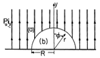 Figure P6.3.6
|
| 6.3.7 | The system shown in cross-section in Fig. P6.3.7 extends to infinity
in the  x and x and  z directions. The electrodes at y = 0 and
y = a + b are shorted. Given Po and the dimensions, what is
E in regions (a) and (b)? z directions. The electrodes at y = 0 and
y = a + b are shorted. Given Po and the dimensions, what is
E in regions (a) and (b)?
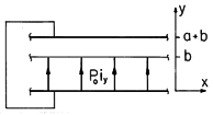 Figure P6.3.7
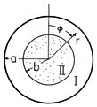 Figure P6.3.8
|
| 6.3.8* | In the two-dimensional configuration shown in Fig. P6.3.8, a
perfectly conducting circular cylindrical electrode at r = a is
grounded. It is coaxial with a rotor of radius b which supports the
polarization density P =  [Po r cos ( [Po r cos ( - -  )]. )].
|
| 6.3.9 | A circular cylindrical material having radius b has the
polarization density P =  [Po (rm+1/bm) cos m [Po (rm+1/bm) cos m ],
where m is a given positive integer. The region b < r < a, shown
in Fig. P6.3.9, is free space. ],
where m is a given positive integer. The region b < r < a, shown
in Fig. P6.3.9, is free space.
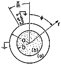 Figure P6.3.9
|
| 6.3.10* | Plane parallel electrodes having zero potential extend to
infinity in the x - z planes at y = 0 and y = d.
| (a) | In a first configuration, the region between the electrodes is free space, except for a
segmented electrode in the plane x = 0 which constrains the potential
there to be V(y). Given V(y), what is the potential distribution in
the regions 0 < x and x < 0, regions (a) and (b), respectively?
|
| (b) | Now the segmented electrode is removed and the region x <
0 is filled with a permanently polarized material having P =
Po ix, where Po is a given constant. What continuity
conditions must the potential satisfy in the x = 0 plane?
|
| (c) | Show that the potential is given by
 (The method used here to represent
  is used in Example 6.6.3.) is used in Example 6.6.3.)
|
|
| 6.3.11 | In Prob. 6.1.1, there is a perfect conductor in the plane y = 0 and
the region d < y is free space. What are the potentials in regions (a)
and (b), the regions where d < y and 0 < y < d, respectively?
|
| | Polarization Constitutive Laws |
|---|
| 6.4.1 | Suppose that a solid or liquid has a mass density of  = 103
kg/m3 and a molecular weight of Mo = 18 (typical of water).
[The number of molecules per unit mass is Avogadro's number (Ao =
6.023 x 1026 molecules/kg-mole) divided by Mo.]
This material has a permittivity = 103
kg/m3 and a molecular weight of Mo = 18 (typical of water).
[The number of molecules per unit mass is Avogadro's number (Ao =
6.023 x 1026 molecules/kg-mole) divided by Mo.]
This material has a permittivity  = 2 = 2 o and is subject to
an electric field intensity E = 107 v/m (approaching the highest
field strength that can be sustained without breakdown on scales of a
centimeters in liquids and solids). Assume that each molecule has a
polarization qd where q = e = 1.6 x 10⁻¹⁹ C, the
charge of an electron). What is |d|? o and is subject to
an electric field intensity E = 107 v/m (approaching the highest
field strength that can be sustained without breakdown on scales of a
centimeters in liquids and solids). Assume that each molecule has a
polarization qd where q = e = 1.6 x 10⁻¹⁹ C, the
charge of an electron). What is |d|?
|
| | Fields in the Presence of Electrically Linear Dielectrics
|
|---|
| 6.5.1* | The plane parallel electrode configurations of Fig. P6.5.1 have
in common the fact that the linear dielectrics have dielectric
"constants" that are functions of x,  = =  (x). The systems have depth c in the z direction.
| (a) | Show
that regardless of the specific functional dependence on x, E is
uniform and simply iy v/d.
|
| (b) | For the system of Fig. P6.5.1a,
where the dielectric is composed of uniform regions having
permittivities  a and a and  b, show that the capacitance is b, show that the capacitance is

|
| (c) | For the smoothly inhomogeneous capacitor of Fig. P6.5.1b,
 = =  o (1 + x/l). Show that o (1 + x/l). Show that

|
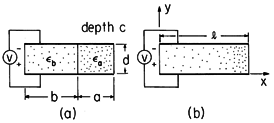 Figure P6.5.1
|
| 6.5.2 | In the configuration shown in Fig. P6.5.1b, what is the
capacitance C if  = =  a (1 + a (1 +  cos cos  x), where 0 < x), where 0 <
 < 1 and < 1 and  are given constants? are given constants?
|
| 6.5.3* | The region of Fig. P6.5.3 between plane parallel perfectly
conducting electrodes in the planes y = 0 and y = l is filled by a
uniformly inhomogeneous dielectric having permittivity  = =  o [1 + o [1 +
 a(1 + y/l)]. The electrode at y = 0
has potential v relative to that at y = l. The electrode separation
l is much smaller than the dimensions of the system in the x and z
directions, so the fields can be regarded as not depending on x or
z. a(1 + y/l)]. The electrode at y = 0
has potential v relative to that at y = l. The electrode separation
l is much smaller than the dimensions of the system in the x and z
directions, so the fields can be regarded as not depending on x or
z.
| (a) | Show that Dy is independent of y.
|
| (b) | With the electrodes having area A, show that the
capacitance is

|
 Figure P6.5.3
|
| 6.5.4 | The dielectric in the system of Prob. 6.5.3 is replaced by one
having permittivity  = =  p exp (- y/d), where p exp (- y/d), where  p is
constant. What is the capacitance C? p is
constant. What is the capacitance C?
|
| 6.5.5 | In the two configurations shown in cross-section in Fig. P6.5.5,
circular cylindrical conductors are used to make coaxial capacitors.
In Fig. P6.5.5a, the linear dielectric has a wedge shape with
interfaces with the free space region that are surfaces of constant
 . In Fig. P6.5.5b, the interface is at r = R. . In Fig. P6.5.5b, the interface is at r = R.
| (a) | Determine E(r) in regions
(1) and (2) in each configuration, showing that simple fields satisfy
all boundary conditions on the electrode surfaces and at the
interfaces between dielectric and free space.
|
| (b) | For lengths l in the z direction, what are the
capacitances?
|
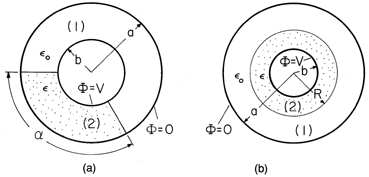 Figure P6.5.5
|
| 6.5.6* | For the configuration of Fig. P6.5.5a, the wedge-shaped
dielectric is replaced by one that fills the gap (over all  as
well as over the radius b < r < a) with material having the
permittivity as
well as over the radius b < r < a) with material having the
permittivity  = =  a + a +  b cos2 b cos2  , where , where
 a and a and  b are constants. Show that the capacitance is b are constants. Show that the capacitance is

|
| | Dielectrics
|
|---|
| 6.6.1* | An insulating sphere having radius R and uniform permittivity
 s is surrounded by free space, as shown in Fig. P6.6.1. It
is immersed in an electric field Eo(t)iz that, in the absence of
the sphere, is uniform. s is surrounded by free space, as shown in Fig. P6.6.1. It
is immersed in an electric field Eo(t)iz that, in the absence of
the sphere, is uniform.
| (a) | Show that the potential is
 where A = (
 s - s -  o )/( o )/( s + 2 s + 2 o ) and B = -3 o ) and B = -3 o /( o /( s + 2 s + 2 o
). o
).
|
| (b) | Show that, in the limit where  s s   , the
electric field intensity tangential to the surface of the sphere goes
to zero. Thus, the surface becomes an equipotential. , the
electric field intensity tangential to the surface of the sphere goes
to zero. Thus, the surface becomes an equipotential.
|
| (c) | Show that the same solution is obtained for the potential
outside the sphere as in the limit  s s   if this
boundary condition is used at the outset. if this
boundary condition is used at the outset.
|
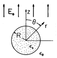 Figure P6.6.1
|
| 6.6.2 | An electric dipole having a z-directed moment p is situated at
the origin, as shown in Fig. P6.6.2. Surrounding it is a spherical
cavity of free space having radius a. Outside of the radius a is a
linearly polarizable dielectric having permittivity  . .
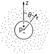 Figure P6.6.2
|
| 6.6.3* | In Example 6.6.1, an artificial dielectric is made from an array
of perfectly conducting spheres. Here, an artificial dielectric is
constructed using an array of rods, each having a circular
cross-section with radius R. The rods run parallel to the
capacitor plates and hence perpendicular to the imposed electric
field intensity. The spacing between rod centers is s, and they are
in a square array. Show that, for s large enough so that the fields
induced by the rods do not interact, the equivalent electric
susceptibility is  c = 2 c = 2 (R/s)2. (R/s)2.
|
| 6.6.4 | Each of the conducting spheres in the artificial dielectric of
Example 6.6.1 is replaced by the dielectric sphere of Prob. 6.6.1.
Again, with the understanding that the spacing between spheres is
large enough to justify ignoring their interaction, what is the
equivalent susceptibility of the array?
|
| 6.6.5* | A point charge finds itself at a height h above an infinite
half-space of dielectric material. The charge has magnitude q, the
dielectric has a uniform permittivity  , and there are no unpaired
charges in the volume of the dielectric or on its surface. The
Cartesian coordinates x and z are in the plane of the dielectric
interface, while y is directed perpendicular to the interface and into
the free space region. Thus, the charge is at y = h. The field in the
free space region can be taken as the superposition of a particular
solution due to the point charge and a homogeneous solution due to a
charge qb at y = -h below the interface. The field in the
dielectric can be taken as that of a charge qa at y = h. , and there are no unpaired
charges in the volume of the dielectric or on its surface. The
Cartesian coordinates x and z are in the plane of the dielectric
interface, while y is directed perpendicular to the interface and into
the free space region. Thus, the charge is at y = h. The field in the
free space region can be taken as the superposition of a particular
solution due to the point charge and a homogeneous solution due to a
charge qb at y = -h below the interface. The field in the
dielectric can be taken as that of a charge qa at y = h.
| (a) | Show that the potential is given by
 where r
 = =  x2 + (y x2 + (y  h)2 + z2 and the magnitudes of
the charges turn out to be h)2 + z2 and the magnitudes of
the charges turn out to be

|
| (b) | Show that the charge is attracted to the dielectric with
the force

|
|
| 6.6.6 | The half-space y > 0 is filled by a dielectric having uniform
permittivity  a, while the remaining region 0 > y is filled by a
dielectric having the uniform permittivity a, while the remaining region 0 > y is filled by a
dielectric having the uniform permittivity  b. Running
parallel to the interface between these dielectrics along the line
where x = 0 and y = h is a uniform line charge of density b. Running
parallel to the interface between these dielectrics along the line
where x = 0 and y = h is a uniform line charge of density
 . Determine the potentials in regions (a) and (b),
respectively. . Determine the potentials in regions (a) and (b),
respectively.
|
| 6.6.7* | If the permittivities are nearly the same, so that (1 -  a / a / b) b)
  is small, the qualitative approach
to determining the field distribution given in connection with Fig.
6.6.7 can be made quantitative. That is, if is small, the qualitative approach
to determining the field distribution given in connection with Fig.
6.6.7 can be made quantitative. That is, if  is small, the
polarization charge induced by the imposed field can be determined to
a good approximation and that charge, in turn, used to find the change
in the applied field. Consider the following approximate
approach to finding the fields in and around the dielectric cylinder
of Example 6.6.2. is small, the
polarization charge induced by the imposed field can be determined to
a good approximation and that charge, in turn, used to find the change
in the applied field. Consider the following approximate
approach to finding the fields in and around the dielectric cylinder
of Example 6.6.2.
|
| 6.6.8 | As an illustration of how identification of the induced
polarization charge can be used in a qualitative determination of the
fields, consider the fields between the plane parallel electrodes of
Fig. P6.6.8. In Fig. P6.6.8a, there are two layers of dielectric.
 Figure P6.6.8
|
| 6.6.9 | The configuration of perfectly conducting electrodes and
perfectly insulating dielectrics shown in Fig. P6.6.9 is similar to
that shown in Fig. 6.6.8 except that at the left and right, the
electrodes are "shorted" together and the top electrode is also
divided at the middle. Thus, the  shaped
electrode is grounded while the shaped
electrode is grounded while the  shaped one is at potential
V. shaped one is at potential
V.
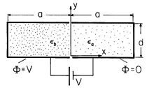 Figure P6.6.9
| (a) | Determine  in regions (a) and (b). in regions (a) and (b).
|
| (b) | With the permittivities equal,
sketch  and E. (Use physical reasoning rather than the
mathematical result.) and E. (Use physical reasoning rather than the
mathematical result.)
|
| (c) | Assuming that the permittivities are nearly
equal, use the result of (b) to deduce  sp on the interface
between dielectrics in the case where sp on the interface
between dielectrics in the case where  a / a / b is
somewhat greater than and then somewhat less than 1. Sketch E
deduced as the sum of the fields induced by these surface charges and
the imposed field. b is
somewhat greater than and then somewhat less than 1. Sketch E
deduced as the sum of the fields induced by these surface charges and
the imposed field.
|
| (d) | With  a much greater that a much greater that  b,
draw a sketch of b,
draw a sketch of  and E in region (b). and E in region (b).
|
| (e) | With  a much less than a much less than  b, sketch b, sketch  and E
in both regions. and E
in both regions.
|
|
| | Smoothly Inhomogeneous Electrically Linear Dielectrics
|
|---|
| 6.7.1* | For the two-dimensional system shown in Fig. P6.7.1, show that
the potential in the smoothly inhomogeneous dielectric is

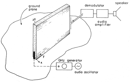 Figure P6.7.1
|
| 6.7.2 | In Example 6.6.3, the dielectrics to right and left, respectively,
have the permittivities  a = a =  p exp (- p exp (- x) and x) and  b = b =  p
exp ( p
exp ( x). Determine the potential throughout
the dielectric regions. x). Determine the potential throughout
the dielectric regions.
|
| 6.7.3 | A linear dielectric has the permittivity
 An electric field that is uniform far from the origin (where it is
equal to Eo iy) is imposed.
| (a) | Assume that  / / o is not much different from unity and find o is not much different from unity and find  p. p.
|
| (b) | With this induced polarization charge as a guide,
sketch E.
|
|
 x(ix +
iy).

 t:
t:
 p, show that the differential charge
conservation law, (10), is indeed satisfied.
 = 0 and
  = -V.
The system extends to infinity in the
  y and
y and  z directions.
 x ix, show that the potential between the electrodes is

 y iy, show that the
potential between the electrodes is

 z directions is shown in Fig. P6.3.2. What is the potential
distribution inside the cylinder of rectangular cross-section?

 /
/ )x]iy. There are
no other field sources in the system and Po and
  are given
constants.
 p = 0 and
  sp = Po cos (2
 x/
x/ ).
).

 (x - xo). In the planes y =
  a,
the potential is constrained to be
  = V cos
  x, where
Po,
  and V are given constants. The region 0 < y < a
is free space and the system extends to infinity in the
  x and
x and
 z directions. Find the potential in regions (a) and (b) in the
free space and polarized regions, respectively. (If you have already
solved Prob. 5.6.12, you can solve this problem by inspection.)

 su =
su =  o. The interior of the
cavity is free space, and Po and
  o are given constants.
The potential far from the cavity is zero. Show that the electric
potential is

 in regions (a) and (b), respectively, outside and inside the
groove.

 x and
x and  z directions. The electrodes at y = 0 and
y = a + b are shorted. Given Po and the dimensions, what is
E in regions (a) and (b)?


 [Po r cos (
 -
-  )].
)].
 I and
I and  II
respectively in the regions outside and inside the rotor are


 =
=  t, where
  is an
angular velocity, the field rotates in the
  direction with this
angular velocity.
 [Po (rm+1/bm) cos m
 ],
where m is a given positive integer. The region b < r < a, shown
in Fig. P6.3.9, is free space.

 . Argue that the resulting potential is obtained by
replacing
 (
( -
-  t).
t).
 /m and has length l in the z direction, and
find vo.

 is used in Example 6.6.3.)
 = 103
kg/m3 and a molecular weight of Mo = 18 (typical of water).
[The number of molecules per unit mass is Avogadro's number (Ao =
6.023 x 1026 molecules/kg-mole) divided by Mo.]
This material has a permittivity
  = 2
= 2 o and is subject to
an electric field intensity E = 107 v/m (approaching the highest
field strength that can be sustained without breakdown on scales of a
centimeters in liquids and solids). Assume that each molecule has a
polarization qd where q = e = 1.6 x 10⁻¹⁹ C, the
charge of an electron). What is |d|?
 =
=  (x). The systems have depth c in the z direction.
 a and
a and  b, show that the capacitance is

 =
=  o (1 + x/l). Show that


 =
=  a (1 +
  cos
cos  x), where 0 <
 < 1 and
  are given constants?
 =
=  o [1 +
 a(1 + y/l)]. The electrode at y = 0
has potential v relative to that at y = l. The electrode separation
l is much smaller than the dimensions of the system in the x and z
directions, so the fields can be regarded as not depending on x or
z.


 =
=  p exp (- y/d), where
  p is
constant. What is the capacitance C?
 . In Fig. P6.5.5b, the interface is at r = R.

 as
well as over the radius b < r < a) with material having the
permittivity
  =
=  a +
a +  b cos2
  , where
 a and
a and  b are constants. Show that the capacitance is

 s is surrounded by free space, as shown in Fig. P6.6.1. It
is immersed in an electric field Eo(t)iz that, in the absence of
the sphere, is uniform.

 s -
s -  o )/(
o )/( s + 2
s + 2 o ) and B = -3
 o /(
o /( s + 2
s + 2 o
).
o
).
 s
s 
 , the
electric field intensity tangential to the surface of the sphere goes
to zero. Thus, the surface becomes an equipotential.
 s
s 
 if this
boundary condition is used at the outset.

 .
.

 and E in regions (a) and (b) outside and inside the cavity.


 , the
electric field intensity tangential to the interface of the dielectric
goes to zero. That is, in this limit, the effect of the dielectric on
the interior fields is the same as if the dielectric were a perfect
conductor.


 if
this boundary condition is used at the outset.
 c = 2
c = 2 (R/s)2.
 , and there are no unpaired
charges in the volume of the dielectric or on its surface. The
Cartesian coordinates x and z are in the plane of the dielectric
interface, while y is directed perpendicular to the interface and into
the free space region. Thus, the charge is at y = h. The field in the
free space region can be taken as the superposition of a particular
solution due to the point charge and a homogeneous solution due to a
charge qb at y = -h below the interface. The field in the
dielectric can be taken as that of a charge qa at y = h.

 =
=  x2 + (y
  h)2 + z2 and the magnitudes of
the charges turn out to be


 a, while the remaining region 0 > y is filled by a
dielectric having the uniform permittivity
  b. Running
parallel to the interface between these dielectrics along the line
where x = 0 and y = h is a uniform line charge of density
 . Determine the potentials in regions (a) and (b),
respectively.
 a /
a / b)
b)

 is small, the qualitative approach
to determining the field distribution given in connection with Fig.
6.6.7 can be made quantitative. That is, if
  is small, the
polarization charge induced by the imposed field can be determined to
a good approximation and that charge, in turn, used to find the change
in the applied field. Consider the following approximate
approach to finding the fields in and around the dielectric cylinder
of Example 6.6.2.
 is zero, the field is
equal to the applied field, both inside and outside the cylinder.
Write this field in polar coordinates.
 sp =
sp =  b Eo
b Eo
 cos
cos  at the surface of the cylinder.

 and show that they are in agreement with this result.
 = (1 -
  a /
a / b) is zero,
what is the imposed E?
 sp induced by this field
at the interface between the dielectrics.
 a >
a >  b,
sketch the field lines in the two regions. (You should be able to see,
from the superposition of the fields induced by this
  sp and
that imposed, which of the fields is the greater.)
 sp and E for the case where
  b >
b >  a.
a.

 shaped
electrode is grounded while the
  shaped one is at potential
V.

 in regions (a) and (b).
 and E. (Use physical reasoning rather than the
mathematical result.)
 sp on the interface
between dielectrics in the case where
  a /
a / b is
somewhat greater than and then somewhat less than 1. Sketch E
deduced as the sum of the fields induced by these surface charges and
the imposed field.
 a much greater that
  b,
draw a sketch of
  and E in region (b).
 a much less than
  b, sketch
  and E
in both regions.


 a =
a =  p exp (-
 x) and
  b =
b =  p
exp (
 x). Determine the potential throughout
the dielectric regions.

 /
/ o is not much different from unity and find
  p.
p.

