The potential distribution for steady conduction is determined by solving (7.4.1)

in a volume V having conductivity  (r) and current
source distribution s(r), respectively.
On the other hand, if the volume is filled by a perfect dielectric
having permittivity  (r) and unpaired charge density
distribution
  u (r), respectively, the
potential distribution is determined by the combination of (6.5.1)
and (6.5.2).

It is clear that solutions pertaining to one of these physical situations are solutions for the other, provided that the boundary conditions are also analogous. We have been exploiting this analogy in Sec. 7.5 for piece-wise continuous systems. There, solutions for the fields in dielectrics were applied to conduction problems. Of course, measurements made on dielectrics can also be used to predict steady conduction phemonena.
Conversely, fields found either theoretically or by experimentation in a steady conduction situation can be used to describe those in perfect dielectrics. When measurements are used, the latter procedure is a particularly useful one, because conduction processes are conveniently simulated and comparatively easy to measure. It is more difficult to measure the potential in free space than in a conductor, and to measure a capacitance than a resistance.
Formally, a quantitative analogy is established by introducing the constant ratios for the magnitudes of the properties, sources, and potentials, respectively, in the two systems throughout the volumes and on the boundaries. With k1 and k2 defined as scaling constants,

substitution of the conduction variables into (2) converts it into (1). The boundary conditions on surfaces S' where the potential is constrained are analogous, provided the boundary potentials also have the constant ratio k2 given by (3).
Most often, interest is in systems where there are no volume
source distributions. Thus, suppose that the capacitance of a pair of
electrodes is to be determined by measuring the conductance of
analogously shaped electrodes immersed in a conducting material. The
ratio of the measured capacitance to conductance, the ratio of
(6.5.6) to (7.2.15), follows from substituting  = k1
= k1 , (3a),

In multiple terminal pair systems, the capacitance matrix defined by (5.1.12) and (5.1.13) is similarly deduced from measurement of a conductance matrix, defined in (7.4.6).
Demonstration 7.6.1. Electrolyte-Tank Measurements
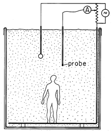
If great accuracy is required, fields in complex geometries are most easily determined numerically. However, especially if the capacitance is sought- and not a detailed field mapping- a conduction analog can prove convenient. A simple experiment to determine the capacitance of a pair of electrodes is shown in Fig. 7.6.1, where they are mounted on insulated rods, contacted through insulated wires, and immersed in tap water. To avoid electrolysis, where the conductors contact the water, low-frequency ac is used. Care should be taken to insure that boundary conditions imposed by the tank wall are either analogous or inconsequential.
Figure 7.6.1 Electrolytic conduction analog tank for determining potential distributions in complex configurations. Often, to motivate or justify approximations used in analytical modeling of complex systems, it is helpful to probe the potential distribution using such an experiment. The probe consists of a small metal tip, mounted and wired like the electrodes, but connected to a divider. By setting the probe potential to the desired rms value, it is possible to trace out equipotential surfaces by moving the probe in such a way as to keep the probe current nulled. Commercial equipment is automated with a feedback system to perform such measurements with great precision. However, given the alternative of numerical simulation, it is more likely that such approaches are appropriate in establishing rough approximations.
Mapping Fields that Satisfy Laplace's Equation
Laplace's equation determines the potential distribution in a volume filled with a material of uniform conductivity that is source free. Especially for two-dimensional fields, the conduction analog then also gives the opportunity to refine the art of sketching the equipotentials of solutions to Laplace's equation and the associated field lines.
Before considering how a sheet of conducting paper provides the medium for determining two-dimensional fields, it is worthwhile to identify the properties of a field sketch that indeed represents a two-dimensional solution to Laplace's equation.
A review of the many two-dimensional plots of equipotentials and
fields given in Chaps. 4 and 5 shows that they form a grid of
curvilinear rectangles.
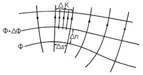
In terms of variables defined for the field sketch of
Fig. 7.6.2, where the distance between equipotentials is denoted by
 n and the distance between E lines is
  s, the ratio
 n/
n/ s tends to be constant, as we shall now show.

The condition that the field be irrotational gives

while the steady charge conservation law implies that along a flux tube,

Thus, along a flux tube,

If each of the flux tubes carries the same current, and if the
equipotential lines are drawn for equal increments of 
 , then
the ratio
  s/
s/ n must be constant throughout the mapping.
The sides of the curvilinear rectangles are commonly made equal,
so that the
equipotentials and field lines form a grid of curvilinear squares.
The faithfulness to Laplace's equation of a map of equipotentials at equal increments in potential can be checked by sketching in the perpendicular field lines. With the field lines forming curvilinear squares in the starting region, a correct distribution of the equipotentials is achieved when a grid of squares is maintained throughout the region. With some practice, it is possible to iterate between refinements of the equipotentials and the field lines until a satisfactory map of the solution is sketched.
Demonstration 7.6.2
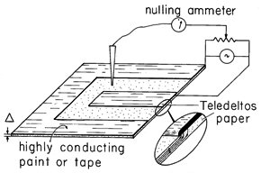
Two-Dimensional Solution to Laplace's Equation by Means of Teledeltos PaperFor the mapping of two-dimensional fields, the conduction analog has the advantage that it is not necessary to make the electrodes and conductor "infinitely" long in the third dimension. Two-dimensional current distributions will result even in a thin-sheet conductor, provided that it has a conductivity that is large compared to its surroundings. Here again we exploit the boundary condition applying to the surfaces of the paper. As far as the fields inside the paper are concerned, a two-dimensional current distribution automatically meets the requirement that there be no current density normal to those parts of the paper bounded by air.
A typical field mapping apparatus is as simple as that shown in Fig. 7.6.3. The paper has the thickness
and a conductivity
. The electrodes take the form of silver paint or copper tape put on the upper surface of the paper, with a shape simulating the electrodes of the actual system. Because the paper is so thin compared to dimensions of interest in the plane of the paper surface, the currents from the electrodes quickly assume an essentially uniform profile over the cross-section of the paper, much as suggested by the inset to Fig. 7.6.3.
Figure 7.6.3 Conducting paper with attached electrodes can be used to determine two-dimensional potential distributions. In using the paper, it is usual to deal in terms of a surface resistance 1/
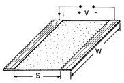
. The conductance of the plane parallel electrode system shown in Fig. 7.6.4 can be used to establish this parameter.
Figure 7.6.4 Apparatus for determining surface conductivity of paper used in experiment shown in Fig. 7.6.3.
The units are simply ohms, and 1/
is the resistance of a square of the material having any sidelength. Thus, the units are commonly denoted as "ohms/square."
To associate a conductance as measured at the terminals of the experiment shown in Fig. 7.6.3 with the capacitance of a pair of electrodes having length l in the third dimension, note that the surface integrations used to define C and G reduce to
where the surface integrals have been reduced to line integrals by carrying out the integration in the third dimension. The ratio of these quantities follows in terms of the surface conductance
as
Here G is the conductance as actually measured using the conducting paper, and C is the capacitance of the two-dimensional capacitor it simulates.
In Chap. 9, we will find that magnetic field distributions as well can often be found by using the conduction analog.


