In a region that has uniform conductivity and permittivity, charge conservation and Gauss' law determine the unpaired charge density throughout the volume of the material, without regard for the boundary conditions. To see this, Ohm's law (7.1.7) is substituted for the current density in the charge conservation law, (7.0.3),

and Gauss' law (6.2.15) is written using the linear polarization constitutive law, (6.4.3).

In a region where  and
and  are uniform, these parameters can
be pulled
outside the divergence operators in these equations. Substitution of
div E found from (2) into (1) then gives the charge relaxation
equation for
  u.
u.

Note that it has not been assumed that E is irrotational, so the unpaired charge obeys this equation whether the fields are EQS or not.
The solution to (3) takes on the same appearance as if it were an ordinary differential equation, say predicting the voltage of an RC circuit.

However, (3) is a partial differential equation, and so the
coefficient of the exponential in (4) is an arbitrary function of
the spatial coordinates. The relaxation time  e
has the typical values illustrated in Table 7.7.1.
 - S/m - S/m |  / / o o |   | |
| Copper | 5.8 x 10⁷ | 1 | 1.5 x 10⁻¹⁹ |
| Water, distilled | 2 x 10⁻⁴ | 81 | 3.6 x 10⁻⁶ |
| Corn oil | 5 x 10-11 | 3.1 | 0.55 |
| Mica | 10-11 - 10-15 | 5.8 | 5.1 - 5.1 x 10⁴ |
The function  i (x, y, z) is the unpaired charge density when t
= 0. Given any initial distribution, the subsequent distribution of
 u is given by (4).
Once the unpaired charge density has decayed to zero
at a given point, it will remain zero. This is true regardless of
the constraints on the surface bounding the region of uniform
  and
and  . Except for a transient that can only be initiated from
very special initial conditions, the unpaired charge density in a
material of uniform conductivity and permittivity is zero. This is
true even if the system is not EQS.
The following example is intended to help emphasize these implications of (3) and (4).
Example 7.7.1. Charge Relaxation in Region of Uniform  and
and

In the region of uniform
and
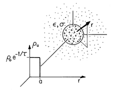
shown in Fig. 7.7.1, the initial distribution of unpaired charge density is
where
o is a constant.
It follows from (4) that the subsequent distribution is
As pictured in Fig. 7.7.1, the charge density in the spherical region r < a remains uniform as it decays to zero with the time constant
e. The charge density in the surrounding region is initially zero and remains so throughout the transient.
Charge conservation implies that there must be a current density in the material surrounding the initially charged spherical region. Yet, according to the laws used here, there is never a net unpaired charge density in that region. This is possible because in Ohmic conduction, there are at least two types of charges involved. In the uniformly conducting material, one or both of these migrate in the electric field caused by the net charge [in accordance with (7.1.5)] while exactly neutralizing each other so that
u = 0 (7.1.6).
Net Charge on Bodies Immersed in Uniform Materials2
2 This subsection is not essential to the material that follows.
The integral charge relaxation law, (1.5.2), applies to the net charge within any volume containing a medium of constant
and
. If an initially charged particle finds itself suspended in a fluid having uniform
and
, this charge must decay with the charge relaxation time constant
e.
Figure 7.7.1 Within a material having uniform conductivity and permittivity, initially there is a uniform charge density u in a spherical region, having radius a. In the surrounding region the charge density is given to be initially zero and found to be always zero. Within the spherical region, the charge density is found to decay exponentially while retaining its uniform distribution.
Demonstration 7.7.1. Relaxation of Charge on Particle in Ohmic Conductor
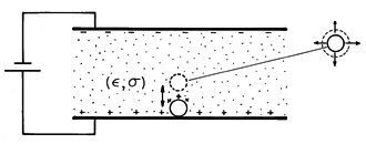
The pair of plane parallel electrodes shown in Fig. 7.7.2 is immersed in a semi-insulating liquid, such as corn oil, having a relaxation time on the order of a second. Initially, a metal particle rests on the lower electrode. Because this particle makes electrical contact with the lower electrode, application of a potential difference results in charge being induced not only on the surfaces of the electrodes but on the surface of the particle as well. At the outset, the particle is an extension of the lower electrode. Thus, there is an electrical force on the particle that is upward. Note that changing the polarity of the voltage changes the sign of both the particle charge and the field, so the force is always upward.
Figure 7.7.2 The region between plane parallel electrodes is filled by a semi-insulating liquid. With the application of a constant potential difference, a metal particle resting on the lower plate makes upward excursions into the fluid. [See footnote 1.] As the voltage is raised, the electrical force outweighs the net gravitational force on the particle and it lifts off. As it separates from the lower electrode, it does so with a net charge sufficient to cause the electrical force to start it on its way toward charges of the opposite sign on the upper electrode. However, if the liquid is an Ohmic conductor with a relaxation time shorter than that required for the particle to reach the upper electrode, the net charge on the particle decays, and the upward electrical force falls below that of the downward gravitational force. In this case, the particle falls back to the lower electrode without reaching the upper one. Upon contacting the lower electrode, its charge is renewed and so it again lifts off. Thus, the particle appears to bounce on the lower electrode.
By contrast, if the oil has a relaxation time long enough so that the particle can reach the upper electrode before a significant fraction of its charge is lost, then the particle makes rapid excursions between the electrodes. Contact with the upper electrode results in a charge reversal and hence a reversal in the electrical force as well.
The experiment demonstrates that as long as a particle is electrically isolated in an Ohmic conductor, its charge will decay to zero and will do so with a time constant that is the relaxation time
/
. According to the Ohmic model, once the particle is surrounded by a uniformly conducting material, it cannot be given a net charge by any manipulation of the potentials on electrodes bounding the Ohmic conductor. The charge can only change upon contact with one of the electrodes.
We have found that a particle immersed in an Ohmic conductor can only discharge. This is true even if it finds itself in a region where there is an externally imposed conduction current. By contrast, the next example illustrates how a unipolar conduction process can be used to charge a particle. The ion-impact charging (or field charging) process is put to work in electrophotography and air pollution control.
Example 7.7.2. Ion-Impact Charging of Macroscopic Particles
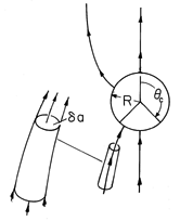
The particle shown in Fig. 7.7.3 is itself perfectly conducting. In its absence, the surrounding region is filled by an un-ionized gas such as air permeated by a uniform z-directed electric field. Positive ions introduced at z
-
then give rise to a unipolar current having a density given by the unipolar conduction law, (7.1.8). With the introduction of the particle, some of the lines of electric field intensity can terminate on the particle. These carry ions to the particle. Other lines originate on the particle and it is assumed that there is no mechanism for the particle surface to initiate ions that would then carry charge away from the particle along these lines. Thus, as the particle intercepts some of the ion current, it charges up.
Figure 7.7.3 Particle immersed in an initially uniform electric field is charged by unipolar current of positive ions following field lines to its surface. As the particle charges, the "window" over which it can collect ions becomes closed. Here the particle-charging process is described as a sequence of steady states. The charge conservation equation (7.0.3) obtained by using the unipolar conduction law (7.1.8) then requires that
Thus, the "field"
E (consisting of the product of the charge density and the electric field intensity) forms flux tubes. These have walls tangential to E and incremental cross-sectional areas
a, as illustrated in Figs.7.7.3 and 2.7.5, such that
E

a remains constant.
As a second approximation, it is assumed that the dominant sources for the electric field are on the boundaries, either on the surface of the particle or at infinity. Thus, the ions in the volume of the gas are low enough in concentration so that their volume charge density makes a negligible contribution to the electric field intensity. At each point in the volume of the gas,
From this statement of Gauss' law, it follows that the E lines also form flux tubes along which E

a is conserved. Because both E

a and
E

a are constant along a given E line, it is necessary that the charge density
be constant along these lines. This fact will now be used to calculate the current of ions to the particle.
At a given instant in the charging process, the particle has a net charge q. Its surface is an equipotential and it finds itself in an electric field that is uniform at infinity. The distribution of electric field for this situation was found in Example 5.9.2. Lines of electric field intensity terminate on the southern end of the sphere over the range


c, where
c is shown in Figs. 7.7.3 and 5.9.2. In view of the unipolar conduction law, these lines carry with them a current density. Thus, there is a net current into the particle given by
Because
is constant along an electric field line and
is uniform far from the charge-collecting particles, it is a constant over the surface of integration.
It follows from (5.9.13) that the normal electric field needed to evaluate (8) is
Substitution of (9) into (8) gives
where, as in Example 5.9.2, qc = 12

o R2 Ea and
Remember,
c is the angle at which the radial electric field switches from being outward to inward. Thus, it is a function of the amount of charge on the particle. Substitution of (11) into (10) and some manipulation gives the net current to the particle as
where
i = 4
o /
.
From (10) it is clear that the current depends on the particle charge. As charge accumulates on the particle, the angle
c increases and so the southern surface over which electric field lines terminate decreases. By the time q = qc, the collection surface is zero and, as implied by (12), the current goes to zero.
If the charging process is slow enough to be viewed as a sequence of stationary states, the current given by (12) is equal to the rate of increase of the particle charge.
Divided by what is on the right and multiplied by the denominator on the left, this expression can be integrated.
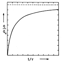
The result is a charging law that is not exponential but rather
Figure 7.7.4 Normalized particle charge as a function of normalized time. The saturation charge qc and charging time are given after (10) and (12), respectively.
This charging transient is shown in Fig. 7.7.4. By contrast with a particle placed in a conduction current that is Ohmic, a particle subjected to a unipolar current will charge up to the saturation charge qc. Note that the charging time,
i = 4
o /
, again takes the form of
divided by a "conductivity."
Demonstration 7.7.2. Electrostatic Precipitation
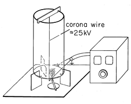
Once dust, smoke, or fume particles are charged, they can be subjected to an electric field and pulled out of the gas in which they are interspersed. In large precipitators used to filter combustion gases before they are released from a stack, the charging and precipitation processes are carried out in one region. The apparatus of Fig. 7.7.5 illustrates this process.
Figure 7.7.5 Electrostatic precipitator consisting of fine wire at high voltage relative to surrounding conducting transparent coaxial cylinder. Ions created in corona discharge in the immediate vicinity of the wire follow field lines toward outer wall, some terminating on smoke particles. Once charged by the mechanism described in Example 7.7.2, the smoke particles are precipitated on the outer wall. A fine wire is stretched along the axis of a grounded conducting cylinder having a radius of 5-10 cm. With the wire at a voltage of 10-30 kv, a hissing sound gives evidence of ionization of the air in the immediate vicinity of the wire. This corona discharge provides positive and negative ion pairs adjacent to the wire. If the wire is positive, some of the positive ions are drawn out of this region and migrate to the cylindrical outer wall. Thus, outside the corona discharge region there is a unipolar conduction current of the type postulated in Example 7.7.2. The ion mobility is typically (1
2) x 10-4 (m/s)/(v/m), while the field is on the order of 5 x 10⁵ v/m, so the ion velocity (7.1.3) is in the range of 50-100 m/s.
Smoke particles, mixed with air rising through the cylinder, can be seen to be removed from the gas within a second or so. Large polyethylene particles dropped in from the top can be more readily seen to collect on the walls. In a practical precipitator, the collection electrodes are periodically rapped so that chunks of the collected material drop into a hopper below.
Most of the time required to clear the air of smoke is spent by the particle in migrating to the wall after it has been charged. The charging time constant
i is typically only a few milliseconds.
This demonstration further emphasizes the contrast between the behavior of a macroscopic particle when immersed in an Ohmic conductor, as in the previous demonstration, and when subjected to unipolar conduction. A particle immersed in a unipolar "conductor" becomes charged. In a uniform Ohmic conductor, it can only discharge.


