As the modern-day versions of the lodestone, which made the existence of magnetic fields apparent in ancient times, permanent magnets are now so cheaply manufactured that they are used at home to pin notes on the refrigerator and so reliable that they are at the heart of motors, transducers, and information storage systems. To a first approximation, a permanent magnet can be modeled by a material having a specified distribution of magnetization density M. Thus, in this section we consider the magnetic field intensity generated by prescribed distributions of M.
In a region where there is no current density J, Ampère's law
requires that H be irrotational. It is then often convenient to
represent the magnetic field intensity in terms of the scalar magnetic
potential  introduced in Sec. 8.3.

From the flux continuity law, (9.2.2), it then follows that  satisfies Poisson's equation.

A specified magnetization density leads to a prescribed
magnetic charge density  m. The situation is analogous to
that considered in Sec. 6.3, where the polarization density was
prescribed and, as a result, where
  p was known.
Of course, the net magnetic charge of a magnetizable body is always zero, because

if the integral is taken over the entire volume containing the body. Techniques for solving Poisson's equation for a prescribed charge distribution developed in Chaps. 4 and 5 are directly applicable here. For example, if the magnetization is given throughout all space and there are no other sources, the magnetic scalar potential is given by a superposition integral. Just as the integral of (4.2.2) is (4.5.3), so the integral of (2) is

If the region of interest is bounded by material on which boundary conditions are specified, (4) provides the particular solution.
Example 9.3.1. Magnetic Field Intensity of a Uniformly Magnetized Cylinder
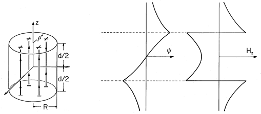
The cylinder shown in Fig. 9.3.1 is uniformly magnetized in the z direction, M = Mo iz. The first step toward finding the resulting H within the cylinder and in the surrounding free space is an evaluation of the distribution of magnetic charge density. The uniform M has no divergence, so
m = 0 throughout the volume. Thus, the source of H is on the surfaces where M originates and terminates. In view of (9.2.3), it takes the form of the surface charge density
The upper and lower signs refer to the upper and lower surfaces.
Figure 9.3.1 (a) Cylinder of circular cross-section uniformly magnetized in the direction of its axis. (b) Axial distribution of scalar magnetic potential and (c) axial magnetic field intensity. For these distributions, the cylinder length is assumed to be equal to its diameter. In principle, we could use the superposition integral to find the potential everywhere. To keep the integration simple, we confine ourselves here to finding it on the z axis. The integration of (4) then reduces to integrations over the endfaces of the cylinder.
With absolute magnitudes used to make the expressions valid regardless of position along the z axis, these integrals become
The field intensity follows from (1)
where u
0 for |z| > d/2 and u
2 for -d/2 < z < d/2. Here, from top to bottom, respectively, the signs correspond to evaluating the field above the upper surface, within the magnet, and below the bottom surface.
The axial distributions of
and Hz shown in Fig. 9.3.1 are consistent with a three-dimensional picture of a field that originates on the top face of the magnet and terminates on the bottom face. As for the spherical magnet (the analogue of the permanently polarized sphere shown in Fig. 6.3.1), the magnetic field intensity inside the magnet has a direction opposite to that of M.
In practice, M would most likely be determined by making measurements of the external field and then deducing M from this field.
If the magnetic field intensity is generated by a combination of prescribed currents and permanent magnetization, it can be evaluated by superimposing the field due to the current and the magnetization. For example, suppose that the uniformly magnetized circular cylinder of Fig. 9.3.1 were surrounded by the N-turn solenoid of Fig. 8.2.3. Then the axial field intensity would be the sum of that for the current [predicted by the Biot-Savart law, (8.2.7)], and for the magnetization [predicted by the negative gradient of (4)].
Example 9.3.2. Retrieval of Signals Stored on Magnetizable Tape
Permanent magnetization is used for a permanent record in the tape recorder. Currents in an electromagnet are used to induce the permanent magnetization, exploiting the hysteresis in the magnetization of certain materials, as will be discussed in Sec. 9.4. Here we look at a model of perpendicular magnetization, an actively pursued research field. The conventional recording is done by producing magnetization M parallel to the tape.
Figure 9.3.2 Permanently magnetized tape has distribution of M representing a Fourier component of a recorded signal. From a frame of reference attached to the tape, the magnetization is static. In a thin tape at rest, the magnetization density shown in Fig. 9.3.2 is assumed to be uniform over the thickness and to be of the simple form
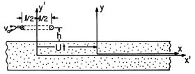
The magnetic field is first determined in a frame of reference attached to the tape, denoted by (x, y, z) as defined in Fig. 9.3.2. The tape moves with a velocity U with respect to a fixed sensing "head," and so our second step will be to represent this field in terms of fixed coordinates. With Fig. 9.3.3 in view, it is clear that these coordinates, denoted by (x' ,y' ,z' ), are related to the moving coordinates by
Thus, from the fixed reference frame, the magnetization takes the form of a traveling wave.
If M is observed at a fixed location x', it has a sinusoidal temporal variation with the frequency
=
U. This relationship between the fixed frame frequency and the spatial periodicity suggests how the distribution of magnetization is established by "recording" a signal having the frequency
.
Figure 9.3.3 From the frame of reference of a sensing coil, the tape is seen to move in the x' direction with the velocity U. The magnetization density has no divergence in the volume of the tape, so the field source is a surface charge density. With upper and lower signs denoting the upper and lower tape surfaces, it follows that
The continuity conditions to be satisfied at the upper and lower surfaces represent the continuity of magnetic flux (9.2.3)
and the continuity of tangential H
In addition, the field should go to zero as y


.
Because the field sources are confined to surfaces, the magnetic scalar potential must satisfy Laplace's equation, (2) with
m = 0, in the bulk regions delimited by the interfaces. Motivated by the "odd" symmetry of the source with respect to the y = 0 plane and its periodicity in x, we pick solutions to Laplace's equation for the magnetic potential above (a), inside (o), and below (b) the tape that also satisfy the odd symmetry condition of having
(y) = -
(-y).
Subject to the requirement that
> 0, the exterior potentials go to zero at y =

. The interior function is made an odd function of y by excluding the cosh (
y) cos (
x) solution to Laplace's equation, while the exterior functions are made odd by making the coefficients equal in magnitude and opposite in sign. Thus, only two coefficients remain to be determined. These follow from substituting the assumed solution into either of (13) and either of (14), and then solving the two equations to obtain
The conditions at one interface are automatically satisfied if those at the other are met. This is a proof that the assumed solutions have indeed been correct. Our foresight in defining the origin of the y axis to be at the symmetry plane and exploiting the resulting odd dependence of
on y has reduced the number of undetermined coefficients from four to two.
This field is now expressed in the fixed frame coordinates. With A defined by (16a) and x and y given in terms of the fixed frame coordinates by (10), the magnetic potential above the tape has been determined to be
Next, we determine the output voltage of a fixed coil, positioned at a height h above the tape, as shown in Fig. 9.3.3. This detecting "head" has N turns, a length l in the x' direction, and width w in the z direction. With the objective of finding the flux linkage, we use (17) to determine the y-directed flux density in the neighborhood of the coil.
The flux linkage follows by multiplying the number of turns N times By integrated over the surface in the plane y = h +
d spanned by the coil.
The dependence on l is clarified by using a trigonometric identity to simplify the last term in this expression.
Finally, the output voltage follows from (9.2.12).
The strong dependence of this expression on the wavelength of the magnetization, 2
/
, reflects the nature of fields predicted using Laplace's equation. It follows from (21) that the output voltage has the angular frequency
=
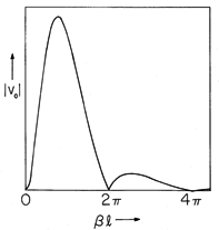
U. Thus, (21) can also be regarded as giving the frequency response of the sensor. The magnitude of vo has the dependence on either the normalized
or
shown in Fig. 9.3.4.
Figure 9.3.4 Magnitude of sensing coil output voltage as a function of l = 2
l/
, where
is the wavelength of the magnetization. If the magnetization is produced by a fixed coil driven at the angular frequency
, the horizontal axis, which is then
l/U, is proportional to the recording frequency.
Two phenomena underlie the voltage response. The periodic dependence reflects the relationship between the length l of the coil and the wavelength 2
/
of the magnetization. When the coil length is equal to the wavelength, there is as much positive as negative flux linking the coil at a given instant, and the signal falls to zero. This is also the condition when l is any multiple of a wavelength and accounts for the sin (

l) term in (21).
The strong decay of the envelope of the output signal as the frequency is increased, and hence the wavelength decreased, reflects a property of Laplace's equation that frequently comes into play in engineering electromagnetic fields. The shorter the wavelength, the more rapid the decay of the field in the direction perpendicular to the tape. With the sensing coil at a fixed height above the tape, this means that once the wavelength is on the order of 2
h, there is an essentially exponential decrease in signal with increasing frequency. Thus, there is a strong incentive to place the coil as close to the tape as possible.
We should expect that if the tape is very thin compared to the wavelength, the field induced by magnetic surface charges on the top surface would tend to be canceled by those of opposite sign on the surface just below. This effect is accounted for by the term [1 + coth (
d)] in the denominator of (21).
In a practical recording device, the sensing head of the previous example would incorporate magnetizable materials. To predict how these affect the fields, we need a law relating the field to the magnetization it induces. This is the subject of the next section.


