Whether we choose to represent the magnetic field in terms of the
magnetic scalar potential  or the vector potential A, in a
current-free region having uniform permeability it assumes a
distribution governed by Laplace's equation. That is, where
  is
constant and J = 0, (9.5.1) and (9.5.2) require that H is
both solenoidal and irrotational. If we let H = -
 ,
the field is automatically irrotational and

is the condition that it be solenoidal. If we let
 H =
H =  x A, the field is automatically
solenoidal. The condition that it also be irrotational (together
with the requirement that A be solenoidal) is
then
 x
x  x A =
x A =  (
(
 A) -
A) -  2 A
2 A

Thus, in Cartesian coordinates, each component of A satisfies the
same equation as does  .
.
The methods illustrated for representing piece-wise uniform dielectrics in Sec. 6.6 are applicable here as well. The major difference is that here, currents are used to excite the field whereas there, unpaired charges were responsible for inducing the polarization. The sources are now the current density and surface current density rather than unpaired volume and surface charges. Thus, the external excitations drive the curl of the field, in accordance with (9.5.1) and (9.5.3), rather than its divergence.
The boundary conditions needed at interfaces between magnetically linear materials are

for the normal component of the magnetic field intensity, and

for the tangential component, in the presence of a surface current. As before, we shall find it convenient to represent windings by equivalent surface currents.
Example 9.6.1. The Spherical Coil with a Permeable Core
The spherical coil developed in Example 8.5.1 is now filled with a uniform core having the permeability
. With the field intensity again represented in terms of the magnetic scalar potential, H = -

, the analysis differs only slightly from that already carried out. Laplace's equation, (1), again prevails inside and outside the coil. At the coil surface, the tangential H again suffers a discontinuity equal to the surface current density in accordance with Ampère's continuity condition, (4). The effect of the permeable material is only felt through the flux continuity condition, (3), which requires that
Thus, the normal flux continuity condition of (8.5.12) is generalized to include the effect of the permeable material by
and it follows that the coefficients needed to evaluate
, and hence H, are now
Substitution of these coefficients into (8.5.10) and (8.5.11) gives the field inside and outside the spherical coil.
If the coil is highly permeable, these expressions show that the field intensity inside is much less than that outside. In the limit of "infinite permeability," where
o /

0, the field inside is zero while that outside becomes
This is the surface current density, (8.5.6). A surface current density backed by a highly permeable material terminates the tangential magnetic field. Thus, Ampère's continuity condition relating the fields to each side of the surface is replaced by a boundary condition on the field on the low permeability side of the interface. Using this boundary condition, that H
a be equal to the given K
, (8.5.6), the solution for the exterior
and H can be written by inspection in the limit when


.
The interior magnetic flux density can in turn be approximated by using this exterior field to compute the flux density normal to the surface. Because this flux density must be the same inside, finding the interior field reduces to solving Laplace's equation for
subject to the boundary condition that
Again, the solution represents a uniform field and can be written by inspection.
The H field, the gradient of the above expression, is indeed that given by (8a) in the limit where
o /
is small. Note that the interior H goes to zero as the permeability goes to infinity, but the interior flux density B remains finite. This fact makes it clear that the inductance of the coil must remain finite, even in the limit where


.
To determine an expression for the inductance that is valid regardless of the core permeability, (8a) can be used to evaluate (8.5.18). Note that the internal flux density B that replaces
o Hz is 3
/[
+ 2
o] times larger than the flux density in the absence of the magnetic material. This enhancement factor increases monotonically with the ratio
/
o but reaches a maximum of only 3 in the limit where this ratio goes to infinity. Once again, we have evidence of the core demagnetization caused by the surface magnetic charge induced on the surface of the sphere.
With the uniformity of the field inside the sphere known in advance, a much simpler derivation of (8a) gives further insight into the role of the magnetization. Thus, in the core, the H-field is the superposition of two fields. The first is caused by the surface current, and given by (8a) with
=
o.
The second is due to the uniform magnetization M = Miz, which is given by the magnetization analog to (6.3.15) (E
H , P

o M ,
o

o ).
The net internal magnetic field intensity is the sum of these.
Only now do we introduce the constitutive law relating Mo to Hz, Mo =
m Hz. [In Sec. 9.8 we will exploit the fact that the relation could be nonlinear.] If this law is introduced into (15), and that expression solved for Hz, a result is obtained that is familiar from from (8a).
This last calculation again demonstrates how the field Ni/3R is reduced by the magnetization through the "feedback factor" 1/[1 + (
m /3)].
Magnetic circuit models, introduced in the next section, exploit the capacity of highly permeable materials to guide the magnetic flux. The example considered next uses familiar solutions to Laplace's equation to illustrate how this guiding takes place. We will make reference to this case study when the subject of magnetic circuits is initiated.
Example 9.6.2. Field Model for a Magnetic Circuit
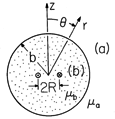
A small coil with N turns and excited by a current i is used to make a magnetic field in a spherically shaped material of permeability
b. As shown in Fig. 9.6.1, the coil has radius R, while the
sphere has radius b and is surrounded by a magnetic medium of permeability
a.
Figure 9.6.1 Sphere of material having uniform permeability with N-turn coil of radius R at its center. Because R b, the coil can be modeled as a dipole. The surrounding region has permeability
a.
Because the coil radius is small compared to that of the sphere, it will be modeled as a dipole having its moment m =
R2 i in the z direction. It follows from (8.3.13) that the magnetic scalar potential for this dipole is
No surface current density exists at the surface of the sphere. Thus, Ampère's continuity law requires that
Also, at the interface, the flux continuity condition is
Finally, the only excitation of the field is the coil at the origin, so we require that the field decay to zero far from the sphere.
Given that the scalar potential has the
dependence cos (
), we look for solutions having this same
dependence. In the exterior region, the solution representing a uniform field is ruled out because there is no field at infinity. In the neighborhood of the origin, we know that
must approach the dipole field. These two conditions are implicit in the assumed solutions
while the coefficients A and C are available to satisfy the two remaining continuity conditions, (18) and (19). Substitution gives two expressions which are linear in A and C and which can be solved to give
We thus conclude that the scalar magnetic potential outside the sphere is that of a dipole
while inside it is that of a dipole plus that of a uniform field.
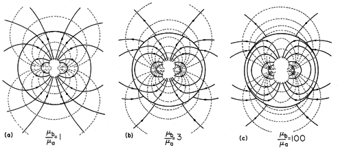
For increasing values of the relative permeability, the equipotentials and field lines are shown in Fig. 9.6.2. With
b/
a = 1, the field is simply that of the dipole at the origin. In the opposite extreme, where the ratio of permeabilities is 100, it has become clear that the interior field lines tend to become tangential to the spherical surface.
Figure 9.6.2 Magnetic potential and lines of field intensity in and around the magnetizable sphere of Fig. 9.6.1. (a) With the ratio of permeabilities equal to 1, the dipole field extends into the surrounding free space region without modification. (b) With b/
a = 3, field lines tend to be more confined to the sphere. (c) With
b/
a = 100, the field lines (and hence the flux lines) tend to remain inside the sphere.
The results of Fig. 9.6.2 can be elaborated by taking the limit of
b /
a going to infinity. In this limit, the scalar potentials are
In the limit of a large permeability of the medium in which the coil is imbedded relative to that of the surrounding medium, guidance of the magnetic flux occurs by the highly permeable medium. Indeed, in this limit, the flux produced by the coil goes to infinity, whereas the flux of the field
H
da escaping from the sphere (the so-called "fringing") stays finite, because the exterior potential stays finite. The magnetic flux
B
da is guided within the sphere, and practically no magnetic flux escapes. The flux lines on the inside surface of the highly permeable sphere can be practically tangential as indeed predicted by (26).
Another limit of interest is when the outside medium is highly permeable and the coil is situated in a medium of low permeability (like free space). In this limit, one obtains
The surface at r = b becomes an equipotential of
. The magnetic field is perpendicular to the surface. The highly permeable medium behaves in a way analogous to a perfect conductor in the electroquasistatic case.
In order to gain physical insight, two types of approximate boundary conditions have been illustrated in the previous example. These apply when one region is of much greater permeability than another. In the limit of infinite permeability of one of the regions, the two continuity conditions at the interface between these regions reduce to one boundary condition on the fields in one of the regions. We conclude this section with a summary of these boundary conditions.

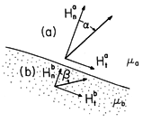
 a and a material having permeability
  b.
b.
At a boundary between regions (a) and (b), having
permeabilities  a and
a and  b, respectively, the normal flux density
 Hn is continuous. If there is no surface current density,
the tangential components Ht are also continuous. Thus, the
magnetic field intensity to either side of the interface is as shown
in Fig. 9.6.3. With the angles between H and the normal on each
side of the interface denoted by
  and
and  , respectively,

The continuity conditions can be used to express tan ( ) in
terms of the fields on the (b) side of the interface, so it follows that

In the limit where  a /
a / b
b  0, there are therefore
two possibilities. Either tan (
 )
)  0, so that

 0 and H in region (a) becomes
perpendicular to the boundary, or tan (
 )
) 
 so that
 90 degrees and H in region (b)
becomes tangential to the boundary. Which of these two possibilities
pertains depends on the excitation configuration.
Excitation in Region of High Permeability
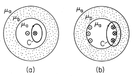
In these configurations, a closed contour can be found within the highly permeable material that encircles current-carrying wires. For the coil at the center of the highly permeable sphere considered in Example 9.6.2, such a contour is as shown in Fig. 9.6.4. As b
b 
 , the flux density
B also goes to infinity. In this limit, the flux escaping from the
body can be ignored compared to that guided by the body. The boundary
is therefore one at which the interior flux density is essentially
tangential.

Once the field has been determined in the infinitely permeable material, continuity of tangential H is used to provide a boundary condition on the free space side of the interface.

Excitation in Region of Low Permeability
In this second class of configurations, there is no closed contour within the highly permeable material that encircles a current-carrying wire. If the current-carrying wires are within the free space region, as in Fig. 9.6.5a, a contour must leave the highly permeable material to encircle the wire. In the limit where b
b 
 , the magnetic field intensity in the
highly permeable material approaches zero, and thus H on the
interior side of the interface becomes perpendicular to the boundary.


With wires on the interface between regions comprising a surface current density, as illustrated in Fig. 9.6.5b, it is still not possible to encircle the current without following a contour that leaves the highly permeable material. Thus, the case of a surface current is also in this second category. The tangential H is terminated by the surface current density. Thus, the boundary condition on H on the interior side of the interface carrying the surface current K is

This boundary condition was illustrated in Example 9.6.1.
Once the fields in the interior region have been found, continuity of normal flux density provides a boundary condition for determining the flux distribution in the highly permeable region.


