Useful links
lab7.tar.gz -- compressed tar archive with all files
Goal
Transmit and receive multiple message streams using frequency-division multiplexing over a shared channel.
Instructions
See Lab #1 for a longer narrative about lab mechanics. The 1-sentence version:
Complete the tasks below, submit your task files on-line before the deadline, and complete your check-off interview within a week of the file submission deadline.
As always, help is available in 32-083 (see the Lab Hours web page).
Task 0: Spectrum plot
For this task just run the code in lab7_0.py to see the plot of the magnitude of the Fourier coefficients for the with_hum.wav file from Lab #6:
import numpy
import waveforms as w

with_hum = w.wavfile('with_hum.wav')
with_hum.spectrum(title='Spectrum with hum',npoints=256000)
w.show()
Interview questions:
Task 1: Amplitude Modulation (2 points)
In this task, we'll transmit a sequence of message bits using a amplitude modulation of a carrier frequency -- your job is to write a Python function am_receive that decodes the transmission and returns a numpy array with the received bits.
The waveforms module provides many useful functions. We'll be using its sampled_waveform object to represent discrete-time waveforms. That object has many methods for manipulating waveforms, some of which are described below as they are needed.
Looking at lab7_1.py, you can see how the transmitter works. First it uses a handy function from the waveforms module to convert the message sequence into a sample sequence, expanding each bit into the specified number of 0/1 samples. The samples are then multiplied by a sine wave at the carrier frequency using the modulate method provided by sampled_waveform objects. This is called amplitude modulation where the amplitude of the carrier is determined directly by the message bits.
am_receive should do the following:
To implement the low-pass filter for a sampled waveform w you can use w.filter('low-pass',cutoff=xxx) which will return a new sampled_waveform as its result. xxx is the cutoff frequency in Hz.
centers = waveforms.samples_to_centers(waveform,
                                       samples_per_symbol=xxx)
where you need to supply the number of samples used to transmit each symbol (in our case each bit).
Use the supplied indices to select the center samples:
bit_sample_array = filtered_demodulated_samples[centers]
lab7_1.py is the template file for this task:
# template tile for Lab #7, Task #1
import numpy
import waveforms as w

# parameters that control the encoding
sample_rate = 1e6
bits_per_second = 30000
samples_per_bit = int(sample_rate/bits_per_second)

# convert message bits into samples, then use samples
# to modulate the amplitude of sinusoidal carrier
def am_transmit(bits,samples_per_bit,fc):
    # use helper function to create a sampled_waveform by
    # converting each bit into samples_per_bit samples
    samples = w.symbols_to_samples(bits,samples_per_bit,
                                   sample_rate)

    # now multiply by sine wave of specified frequency
    return samples.modulate(hz=fc)

# receive amplitude-modulated transmission:
def am_receive(samples,fc,samples_per_bit):
    pass # your code here

if __name__ == '__main__':
    message_size = 32

    # a random binary message
    message = numpy.random.randint(2,size=message_size)

    # run transmitter
    fc = 125e3  # carrier frequency
    xmit_out = am_transmit(message,samples_per_bit,fc)

    # plot spectrum of transmitted message
    xmit_out.spectrum(title='spectrum of received samples',
                      npoints=256000)

    # run receiver
    received = am_receive(xmit_out,fc,samples_per_bit)

    # report results
    print 'message: ',message
    print 'received:',received
    if not numpy.array_equal(message,received):
        print 'differences'
    else:
        print 'message received okay'

    # display the plots
    w.show()
Interview question:
Task 2: Multiple Transmitters (2 points)
Using the receiver you built in Task #1, let's see what happens if we add second transmitter to the shared channel. For this task and the following tasks we'll assume a channel spacing of 50 kHz. Start by running the code in lab7_2.py:
# template tile for Lab #7, Task #2

import numpy
import waveforms as w

from lab7_1 import samples_per_bit,am_transmit,am_receive

if __name__ == '__main__':
    message_size = 32

    # two random binary messages
    message1 = numpy.random.randint(2,size=message_size)
    message2 = numpy.random.randint(2,size=message_size)

    # run transmitters
    fc1 = 125e3  # carrier frequency
    xmit1 = am_transmit(message1,samples_per_bit,fc1)

    fc2 = 175e3  # carrier frequency
    xmit2 = am_transmit(message2,samples_per_bit,fc2)

    # combine results on shared channel, plot spectrum
    rf = xmit1 + xmit2
    rf.spectrum(title='spectrum of shared channel',
                npoints=256000)

    # run receiver for channel 1
    receive1 = am_receive(rf,fc1,samples_per_bit)

    # report results
    print 'message: ',message1
    print 'received:',receive1
    if not numpy.array_equal(message1,receive1):
        print 'differences'
    else:
        print 'message received okay'

    # display the plots
    w.show()
The receiver fails and examining the spectrum of the demodulated signal reveals what needs fixing: the cutoff frequency for the receiver's low-pass filter has to be adjusted to eliminate the information from other transmitters in addition to the information at 2*fc of the desired channel. Remove the import of the Task #1 functions, copy over the code and constant definitions from Task #1, make the appropriate change to the low-pass filter in am_receive and rerun the Task #2 code to demodulate and receive the first transmission correctly (and ignore the second transmission).
How should the new cutoff frequency for the receiver's low-pass filter be related to the spacing of transmit frequencies? Remember that real filters don't have a perfect frequency response, i.e., the amplitude above the cutoff frequency doesn't drop from 1 to 0 instantaneously. So you should leave a little "forbidden zone" between the receive bands for each transmitter. Does you revised receiver work now? (It should.)
The low-pass filter in the receiver is used to eliminate parts of the receive spectrum that contain information from other transmitters using the shared channel. However, it doesn't eliminate information from other transmitters that falls in the same frequency range as the transmitter we're trying to receive. High-frequency components from the fast edges in the messages from other transmitters extends over the whole spectrum. But since the amplitude of those high-frequencies components is small, it just looks like noise to other receivers. If there are a sufficiently large number of other transmitters, this noise may actually be non-negligible.
To clean up our act, we'll apply the same low-pass filter to the samples in the transmitter before we use them to modulate the carrier sine wave. Here's a list of reasons for doing so:
Make the appropriate addition to am_transmit and rerun the tests.
Interview question:
Task 3: Transmission Rate vs. Bandwidth (1 point)
Copy your code from Task #2 and place it in the Task #3 template lab7_3.py
# template tile for Lab #7, Task #3
import numpy
import waveforms as w

# copy over the body (non-test code) from your Task #2
# and put it here!

if __name__ == '__main__':
    n = 10  # no. of bits of ISI to test for
    # generate all possible n-bit sequences
    message = [0] * (n * 2**n)
    for i in xrange(2**n):
        for j in xrange(n):
            message[i*n + j] = 1 if (i & (1<<j)) else 0
    message = numpy.array(message,dtype=numpy.int)

    # run transmitter
    fc = 125e3
    xmit = am_transmit(message,samples_per_bit,fc)

    # run receiver
    receive = am_receive(xmit,fc,samples_per_bit)

    # report results
    print 'message: ',message
    print 'received:',receive
    if not numpy.array_equal(message,receive):
        print 'differences'
    else:
        print 'message received okay'

    # display the plots
    w.show()
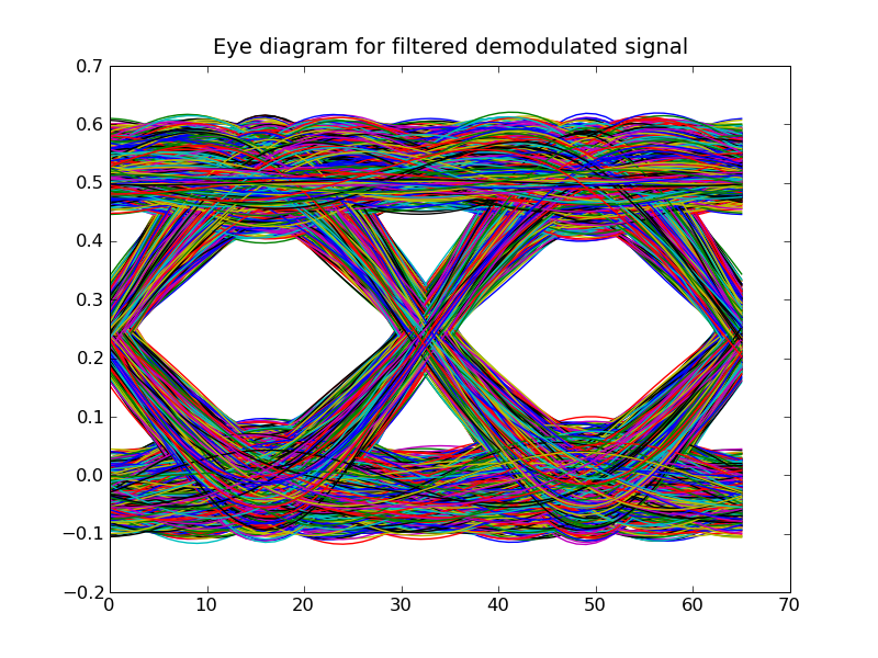
Modify your am_receive to plot an eye
diagram for the output of the low-pass filter using
sig.eye_diagram(samples_per_bit,
                title="Eye diagram for filtered demodulated signal")
where sig is the sampled_waveform returned by the low-pass filter and samples_per_bit is the number of samples transmitted for each bit (used to determine how many samples to plot for each pass of the eye diagram). You can comment out the lines that produce the spectrum plots.
When you run the code, you should see something like the following figure:
The eye has narrowed because of inter-symbol interference introduced by the low-pass filters. Try changing bits_per_second at the top of the file from 30,000 to 40,000. Rerun the code and describe how the eye changes.
Try different values for bits_per_second to get an estimate for the maximum number of bits per second that we can transmit over this band-limited channel.
Interview question:
Task 4: Transmission Delays (1 point)
Up until now we've been dealing with an ideal shared channel with ISI but no channel-induced noise or transmission delays. Noise and ISI in shared channels are no different than they were when we worried about them in our dedicated wire channels: we can see their effects on the eye diagram for our "piece" of the shared channel and can adjust the transmission rate appropriately to create the most open eye possible.
Transmission delay introduces a slightly different problem as
illustrated by the following code in lab7_4.py:
Run this code: the message is received incorrectly. In fact,
every received bit has been flipped from the original message bit!
Interview questions:
Task 5: Dealing with transmission delays (4 points)
In this task your job is to design a transmitter and receiver
that work correctly in the face of unknown transmission delays.
Your code should include both the transmitter and receiver
low-pass filters described in Task #2.
lab7_5.py is a template file for this task.
The code tests your implementation with many different transmission
delays -- your code should work unchanged for all the tests.
Hint: Depending on the transmission delay, demodulating using some
fixed-phase sinusoid at the carrier frequency will result in
To successfully demodulate the received signal, your receiver
should iteratively try demodulating with carriers of with different
phase offsets and check whether the resulting received bit sequence is
"correct" -- four well-chosen offsets should be sufficient. Of
course, the receiver doesn't know what message was sent, so it cannot
tell what's "correct" as things stand. Hence, you should modify both
the transmitter and receiver to include some additional, known message
bits that can help the receiver determine when the received bit
sequence is correct. Think about the tools you have learned in
earlier labs in the course that can help here.
# template tile for Lab #7, Task #4
import numpy
import waveforms as w

from lab7_2 import samples_per_bit,am_transmit,am_receive

if __name__ == '__main__':
    message_size = 32

    # a random binary message
    message = numpy.random.randint(2,size=message_size)

    # run transmitter
    fc = 125e3  # carrier frequency
    xmit_out = am_transmit(message,samples_per_bit,fc)

    # plot spectrum of transmitted message
    xmit_out.spectrum(title='spectrum of received samples',
                      npoints=256000)

    ##################################################
    ## ADDED FOR TASK #4: a transmission delay
    ##################################################
    delayed_xmit_out = xmit_out.delay(nsamples=4)

    # run receiver
    received = am_receive(delayed_xmit_out,fc,samples_per_bit)

    # report results
    print 'message: ',message
    print 'received:',received
    if not numpy.array_equal(message,received):
        print 'differences'
    else:
        print 'message received okay'

    # display the plots
    w.show()
# template tile for Lab #7, Task #5
import numpy
import waveforms as w

# parameters that control the encoding
sample_rate = 1e6
bits_per_second = 30000
samples_per_bit = int(sample_rate/bits_per_second)

# convert message bits into samples, then use samples
# to modulate the amplitude of sinusoidal carrier
def am_transmit(bits,samples_per_bit,fc):
    pass # your code here

# receive amplitude-modulated transmission:
def am_receive(samples,fc,samples_per_bit):
    pass # your code here

if __name__ == '__main__':
    message_size = 32

    # a random binary message
    message = numpy.random.randint(2,size=message_size)

    # run transmitter
    fc = 125e3  # carrier frequency
    xmit_out = am_transmit(message,samples_per_bit,fc)

    ##################################################
    ## ADDED FOR TASK #5: try different transmission delays
    ##################################################
    for delay in xrange(8):
        print "%d-sample delay:" % delay
        delayed_xmit_out = xmit_out.delay(nsamples=delay)

        # run receiver
        received = am_receive(delayed_xmit_out,fc,samples_per_bit)

        # report results
        print '    message: ',message
        print '    received:',received
        if not numpy.array_equal(message,received):
            print '    => differences'
        else:
            print '    => message received okay'