Problem .
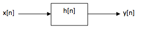
Consider an LTI system characterized by the unit-sample response h[n].
Given an expression for the frequency response of the system H(ejΩ)
in terms of h[n].
H(ejΩ) = &Sigmam h[m]e-jΩm
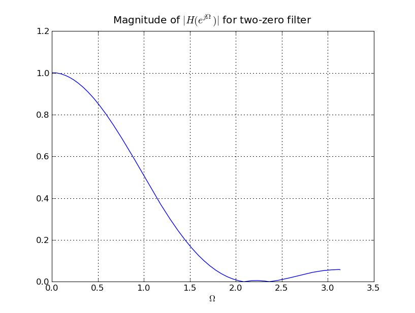
If h[0]=1, h[1]=0, h[2]=1, and h[n]=0 for all other n, what is H(ejΩ)?
H(ejΩ) = 1 + e-2jΩ
Let h[n] be defined as in part B and
x[n] = cos(Ω1)n).
Is there a value of &Omega1 such that y[n]=0 for all n and
0 ≤ &Omega1 ≤ π?
Ω1 = π/2
Find the maximum magnitude of y[n] if x[n] = cos(πn/4).
Maximum magnitude of y[n] is sqrt(2).
Find the maximum magnitude of y[n] if x[n] = cos(-πn/2).
Maximum magnitude of y[n] is 0.
Problem .
Suppose we want to design a filter whose frequency response is zero at
Ω1 = 2π/3 and Ω2 = 3π/4.
Make a qualitative sketch of the filter's frequency response. Would you
characterize the filter as low-pass or high-pass?
This is a low-pass filter.
Let h[n] be the unit-sample response of the filter.
For what value of N is h[n] = 0 for n ≥ N?
5. To achieve the desired frequency response we need a response that has
zeros at ej2Ω/3, e-j2Ω/3, ej3Ω/4,
and e-j3Ω/4, i.e., a response of the form
H(ejΩ) = h[0] + h[1]z + h[2]z2 + h[3]z3 + h[4]z4
Derive the unit-sample response of the filter. Don't worry about scaling
the response (yet).
We use two single-zero filters in series, each with a unit-sample response of the
form h = [1,-2cosΩ,1]. The overall unit-sample response can be
calculated by convolving the two single-zero responses.
h[0] = 1
h[1] = 1 + sqrt(2)
h[2] = 2 + sqrt(2)
h[3] = 1 + sqrt(2)
h[4] = 1
h[n] = 0 for all other n
What is the appropriate scale factor for the unit-sample response above
that will ensure that H(ejΩ) ≤ 1.
The maximum magnitude of the filter response occurs at Ω=0. We want
to scale the response so that H(ej0) = 1. In this case
z = ej0 = 1 so
The appropriate scale factor for the h[n] is the reciprocal of this value.
To improve the quality of the filter, we want to add a pole at Ω = π/2.
Choose an appropriate value for r, the magnitude of the pole, and give the
difference equation for the combined 2-zero, 1-pole filter.
The difference equation for the combined system is
Problem .
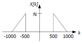
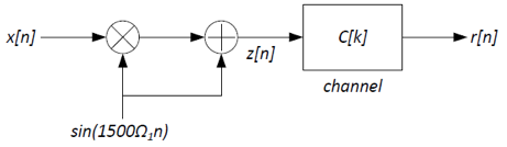
In this problem we explore the form of modulation/demodulation for a
class of signals known as bandpass signals. Consider a signal x[n]
that repeats periodically with period N=8001 and has purely real
Fourier coefficients X[k] shown below.
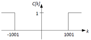
We wish to transmit the signal x[n] over a communication channel.
The channel acts as a high-pass filter with frequency response C[k]
that is 0 for k ≤ 1001 and is 1 elsewhere as shown below:
We would like to use synchronous modulation/demodulation in a way
that does not require the receiver to have its own local oscillator
that would have to maintain phase synchronization with the
transmitter. The transmitter uses the modulation system depicted
below (Ω1 = 2π/8001):
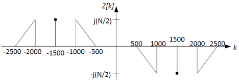
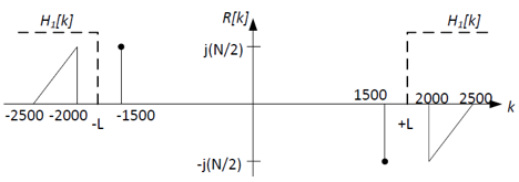
Sketch Z[k] and R[k], the Fourier coefficients of the signals
z[n] and r[n], respectively. Clearly label your
sketches.
When modulating a signal that has purely real Fourier coefficients by a sine wave
which has purely imaginary coefficients, we get a signal that has purely imaginary
coefficients. The resulting spectrum will have two copies of X[k]: one
scaled by jN/2 centered around k=-1500, and one scaled by -jN/2
centered around k=+1500. The addition of the sine wave itself to the signal adds
two non-zero coeffients at k=-1500 and k=1500:
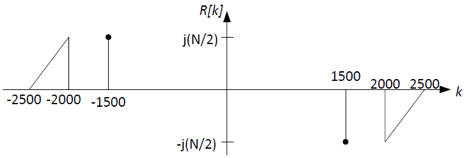
You can get R[k] by applying the high-pass filter C[k] to
Z[k]. Note that R[k] has both (1) part of the original signal,
X[k], and (2) the carrier signal, sin(1500Ω1n).
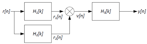
The receiver/demodulator that we would like to use has the following structure:
Where H1[k] is an ideal high-pass filter shown below:
Using ideal low-pass, high-pass, and/or band-pass filters, sketch
the frequency responses H2[k] and H3[k], as well as
the index of the cutoff frequency, L, for H1(f) so
that y[n]=x[n]. Also sketch V[k], the Fourier
coefficients of the intermediate signal v[n].
The idea here is to use H1[k] and H2[k] to separate the signal from
the carrier contained in R[k]. Given H1[k] is a high-pass filter, we
can use it to remove the carrier part and retain the signal part, as
shown below. Choose L in the range 1501-1999; let's use L=1750.
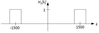
To get the carrier part, we can need to remove the signal part.
Thus we can use either a band-pass filter or a low-pass filter for
H2[k]. Let's use a band-pass filter centered at the carrier
frequency, k=±1500, shown below:
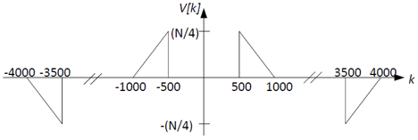
Now that the signal and carrier parts have been separated, we can
use the carrier part to demodulate the signal part back to baseband by
multiplying the carrier and signal parts together. Recall that this
is the same as frequency-shifting the signal part by ±1500 and scaling
by ±1/(2j). The result, v[n], has the Fourier coefficients V[k] shown
below:
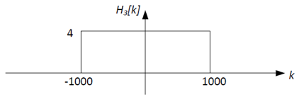
This is almost the same as the original signal's Fourier
coefficients X[k], except that (1) the amplitude is scaled by 1/4, and
(2) there are some additional high frequency components . We can use
the filter H3[k] to correct for these things. A low-pass filter with
a gain of 4 and a cutoff at k=±1000 will do the job:
Problem .
Consider a binary convolutional code specified by the generators (1011, 1101,
1111).
What are the values of
constraint length of the code
rate of the code
number of states at each time step of the trellis
number of branches transitioning into each state
number of branches transitioning out of each state
number of expected parity bits on each branch
4
1/3
24-1 = 8
2
2
3
A 10000-bit message is encoded with the above code and transmitted
over a noisy channel. During Viterbi decoding at the receiver, the
state 010 had the lowest path metric (a value of 621) in the final
time step, and the survivor path from that state was traced back to
recover the original message.
What is the likely number of bit errors that are corrected by the
decoder? How many errors are likely left uncorrected in the decoded
message?
621 errors were likely corrected by the decoder to
produce the final decoded message. We cannot infer the number of
uncorrected errors still left in the message absent more information
(like, say, the original transmitted bits).
If you are told that the decoded message had no uncorrected errors, can you
guess the approximate number of bit errors that would have occured had the
10000 bit message been transmitted without any coding on the same
channel?
3*10000 bits were transmitted over the channel and the received
message had 621 bit errors (all corrected by the convolutional
code). Therefore, if the 10000-bit message would have been transmitted without
coding, it would have had approximately 621/3 = 207 errors.
From knowing the final state of the trellis (010, as given
above), can you infer what the last bit of the original message
was? What about the last-but-one bit? The last 4 bits?
The state gives the last 3 three bits of the original message. In general,
for a convolutional code with a constraint length k, the state indicates
the final k-1 bits of the original message. To determine
more bits we would need to know the states along the most-likely path as
we trace back through the trellis.
Consider a transition branch between two states on the trellis that
has 000 as the expected set of parity bits. Assume that 0V and 1V
are used as the signaling voltages to transmit a 0 and 1
respectively, and 0.5V is used as the digitization threshold.
Assuming hard decision decoding, which of the two set of
received voltages will be considered more likely to correspond to
the expected parity bits on the transition: (0V, 0.501V, 0.501V) or
(0V, 0V, 0.9V)? What if one is using soft decision decoding?
With hard decision decoding: (0V, 0.501V, 0.501V) -> 011 -> hamming
distance of 2 from expected parity bits. (0V, 0V, 0.9V) -> 001 ->
hamming distance of 1. Therefore, (0V, 0V, 0.9V) is considered more
likely.
With soft decision decoding, (0V, 0.501V, 0.501V) will have a
branch metric of approximately 0.5. (0V, 0V, 0.9V) will have a
metric of approximmately 0.8. Therefore, (0V, 0.501V, 0.501V) will
be considered more likely.
Problem .
Indicate whether each of the statements below is true or false, and a
brief reason why you think so.
If the number states in the trellis of a convolutional code is
S, then the number of survivor paths at any point of time is S.
True. There is one survivor per state.
The path metric of a state s1 in the trellis indicates the
number of residual uncorrected errors left along the trellis path from
the start state to s1.
False. It indicates the number of likely corrected errors.
Among the survivor paths left at any point during the decoding,
no two can be leaving the same state at any stage of the trellis.
False. In fact, the survivor paths will likely merge at a
certain stage in the past, at which point all of then will emerge
from the same state.
Among the survivor paths left at any point during the decoding,
no two can be entering the same state at any stage of the trellis.
True. When two paths merge at any state, only one of them
will ever be chosen as a survivor path.
For a given state machine of a convolutional code, a particular
input message bit stream always produces the same output parity bits.
False. The same input stream with different start states
will produce different output parity bits.
Problem .
Consider an LTI system A that has the following difference equation
relationship between its input samples x[n] and output
samples y[n]:
y[n] = (1/4) * (x[n] - 2x[n-1] + x[n-2])
What is the unit sample response of the system?
h[0] = 1/4
h[1] = -1/2
h[2] = 1/4
h[n] = 0 for all other n
Write an expression for the frequency response of this system as a
polynomial in z = e-jΩ.
Using the unit sample response, one can derive the frequency
response as H(z) = (1/4) * (z2 - 2z + 1).
For which frequencies does this system serve as a notch filter? In
other words, for what values of Ω is the frequency response of
the system equal to zero?
The frequency response of the system is zero at z = 1, or
e-jΩ = 1, or Ω = 0.
Thus this system eliminates the zero frequency (DC component) in any signal.
What is response of the system to the input x[n] = 1n?
Ans: 1n is equivalent to the complex exponential ejΩn for
Ω=0. Because the frequency response of the system is zero at Ω=0, the
output of the system is y[n]=0 for all n. One can also verify this by
using flip-and-slide to convolve 1n with the unit sample response.
Now consider a second LTI system B whose unit sample response is given
by
h[n] = (1/2)n for n ≥ 0
h[n] = 0 for n < 0
Express the relationship between the inputs x[n] and outputs y[n]
of the system in the form of a difference equation.
From the standard convolution equation we get
Note that because the unit sample response is infinite, we cannot
write a finite difference equation using x[n] alone, as we did for
system A above, and have to use a feedback term y[n-1].
Write an expression for the frequency response of this system as a
polynomial in z = e-jΩ.
style="display:none">
Substitute x[n] = ejΩn and
y[n] = H(ejΩ)ejΩn
into the difference equation above, divide by ejΩn on both sides, and rearrange (as we
did in class), to get the following expression:
H(z) = 1/(1-0.5*z) where z = e-jΩ
What is the frequency response of this system at
Ω = 0,
Ω = π/2, and
Ω = π.
For which frequencies does this system serve as a notch filter? In
other words, for what values of Ω is the frequency response of
the system equal to zero?
The frequency response of this system is nonzero for all frequencies.
Now suppose systems A and B are connected in series, i.e., the output
of system A is fed as input to system B.
What is the difference equation that relates the input of the
combined system x[n] with its output y[n]?
y[n] - 0.5*y[n-1] = (1/4) * (x[n] - 2x[n-1] + x[n-2])
What is the unit sample response of the combined system?
The unit sample response of the combined system is obtained by
convolving the individual unit sample responses (using, say, flip
and slide). Note that the unit sample response of the combined
system is not finite because the difference equation has feedback terms.
h[n] = 0 for n < 0
h[0] = 1/4
h[1] = -3/8
h[n] = (1/4)*(1/2)n - (1/2)*(1/2)n-1 + (1/4)*(1/2)n-2  for n ≥ 2
     = (1/2)n+2
Write down the frequency response of the combined system in terms
of a polynomial in z = e-jΩ.
H(z) = (1/4)*(z2 - 2z + 1) / (1 - 0.5*z)
What is the response of the combined system to the input
x[n] = (-1)n?
(-1)n = ejΩn for Ω = π
At Ω = π, z = -1, H(z) = 2/3. Therefore, output y[n] = (2/3)*(-1)n.
Problem .
Suppose management has decided to use 20-bit data blocks in the
company's new (20,k,3) error correcting code. What's the maximum value
of k that will permit the code to be used for single bit error
correction, i.e., that will achieve a minimum Hamming distance of 3
between code words?
n and k must satisfy the constraint that n ≤ 2n-k-1.
If n=20 then a little trial-and-error search finds k=15.
Problem .
Consider the following (n,k,d) block code:
where D0-D14 are data bits, P0-P2 are row parity bits, P3-P7 are column parity
bits and P8 is the parity of all the other bits in the message. The transmitted code word will be:
D0 D1 D2 ... D13 D14 P0 P1 ... P6 P7 P8
Please give the values for n, k, d for the code above.
n=24, k=15, d=4.
To see why d is 4, consider two non-identical 15-bit messages, A and B:
If hamming(A,B)=1, one of the data bits has flipped. That
means that three of the parity bits will be different: the row and column
parity for the flipped data bit, and the overall parity bit. So
there's a total of 4 bits that change when the message changes by 1
bit. In this case the Hamming distance between the original and new
code words is 4.
If hamming(A,B)=2, two of the data bits have flipped. In the
worst case, if the
two bits are in the same row, two of the column parity bits will be
different; if they are in the same column, two of the row parity bits
will be different. Again at least of 4 bits change and again the
Hamming distance between the original and new code words will be 4.
If hamming(A,B)=3, three of the data bits have flipped. In
the worst case, the bits are positioned so that two of them are
in the same row (so the row parity doesn't change) and two of them
are in the same column (so the column parity doesn't). But
the overall parity bit will be different, but that's still a
total of 4 changed bits, so the two resulting code words have a
Hamming distance of 4.
If hamming(A,B)≥4, the two code words will of course have
a Hamming distance of at least 4.
Conclusion: Code words produced from different 15-bit messages have a
Hamming distance of at least 4.
For each of received code words, indicate the number of errors. If there are errors,
indicate if they are correctable, and if they are, what the correction should be.
The syndrome bits are shown in red. There are two errors detected,
one in P4 and one in P8. The P8 error indicates that there's a
single-bit error in the other message bits; and since there's only
one other error -- the parity bit P4 -- it must be that parity
bit itself that had the error. So the correct data bits are:
Here the error in P8 indicates a correctable single-bit
error, and the row and column parity bit indicate the data
bit which got flipped (D1). Flipping it gives us the
correct data bits:
M4: 0 0 0 1 0, 0 1 0 0 1, 1 0 0 0 1
Problem .
Consider two convolutional coding schemes - I and II. The generator polynomials for
the two schemes are
Notation is follows: if the generator polynomial is, say, 1101, then
the corresponding parity bit for message bit n is
x[n] xor x[n-1] xor x[n-3]
where x[n] is the message sequence.
Indicate TRUE or FALSE
Code rate of Scheme I is 1/4.
Constraint length of Scheme II is 4.
Code rate of Scheme II is equal to code rate of Scheme I.
Constraint length of Scheme I is 4.
The code rate (r) and constraint length (k) for the two schemes are
I: r = 1/2, k = 4
II: r = 1/2, k = 6
So
false
false
true
true
How many states will there be in the state diagram for Scheme I? For Scheme II?
Number of states is given by 2k-1 where k = constraint length. Following the
convention of state machines as outlined in Lecture 10, number of states in
Scheme I is 8 and in Scheme II, 32.
Which code will lead to a lower bit error rate? Why?
Scheme II is likely to lead to a lower bit error rate. Both codes have the same code
rate but different constraint lengths. So Scheme II encodes more history and since
it is less likely that 6 trailing bits will be in error vs. 4 trailing bits, II is stronger.
Alyssa P. Hacker suggests a modification to Scheme I which
involves adding a third generator polynomial G2 = 1001. What is the
code rate r of Alyssa's coding scheme? What about constraint
length k? Alyssa claims that her scheme is stronger than
Scheme I. Based on your computations for r and k, is
her statement true?
For Alyssa's scheme r = 1/3, k = 4. Alyssa's code
has a lower code rate (more redundancy), and given then she's
sending additional information, the modified scheme I is
stronger in the sense that more information leads to better error
detection and correction.
Problem .
Consider a convolution code that uses two generator polynomials: G0 = 111 and G1 = 110.
You are given a particular snapshot of the decoding trellis used to determine the most
likely sequence of states visited by the transmitter while transmitting a particular
message:
Complete the Viterbi step, i.e., fill in the question marks in the matrix, assuming
a hard branch metric based on the Hamming distance between expected an received parity
where the received voltages are digitized using a 0.5 V threshold.
The digitized received parity bits are 1 and 0.
Complete the Viterbi step, i.e., fill in the question marks in
the matrix, assuming a soft branch metric based on the square of the
Euclidean distance between expected an received parity voltages. Note that your
branch and path metrics will not necessarily be integers.
Does the soft metric give a different answer than the hard metric? Base your
response in terms of the relative ordering of the states in the second column and
the survivor paths.
The soft metric certainly gives different path metrics, but the relative ordering
of the likelihood of each state remains unchanged. Using the soft metric, the
choice of survivor path leading to states 2 and 3 has firmed up (with the hard
metric either of the survivor paths for each of states 2 and 3 could have been
chosen).
Problem .
Single-sideband (SSB) modulation is a modulation technique designed to
minimize the amount of footprint used to transmit an amplitude
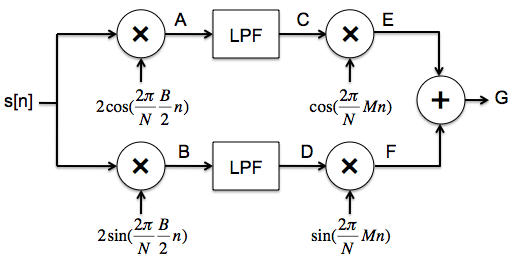
modulated signal. Here's one way to implement an SSB transmitter.
Starting with a band-limited signal s[n], modulate it with two carriers,
one phase shifted by π/2 from the other. The modulation frequency is chosen
to be B/2, i.e., in the middle of the frequency range of the signal to be transmitted.
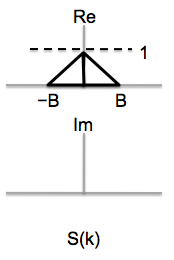
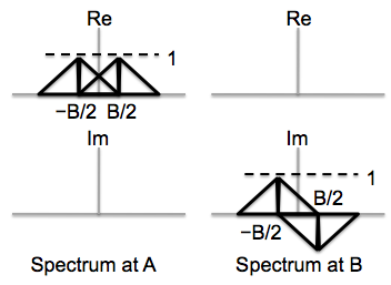
Sketch the real and imaginary parts of the Fourier coefficients for the
signals at points A and B. The figure below shows the Fourier coefficients for
the signal s[n].
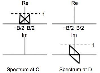
The modulated signal is now passed through a low-pass filter with a
cutoff frequency of B/2. Sketch the real and imaginary parts of the Fourier coefficients for the
signals at points C and D.
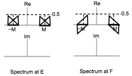
The signal is modulated once again to shift it up to the desired
transmission frequency. Sketch the real and imaginary parts of the Fourier coefficients for the
signals at points E and F.
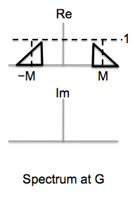
Finally the two signals are summed to produce the signal to be sent over
the air. Sketch the real and imaginary parts of the Fourier coefficients for the
signal at point G.
Problem .
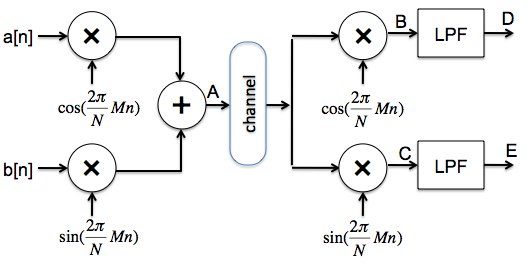
We learned in lecture that if we modulate a signal with a cosine of a particular frequency and
then demodulate with a sine of the same frequency and pass the result through
a low-pass filter, we get nothing! We can use this effect to our advantage -- here's
a modulation/demodulation scheme that sends two independent signals over a single
channel using the same frequency band:
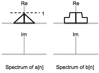
The Fourier coefficients for signals a[n] and b[n] are
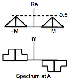
show below. Sketch the real and imaginary parts of the Fourier coefficients for the
signal at point A.
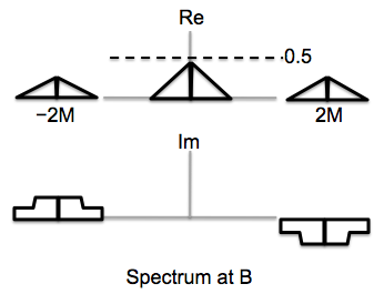
Sketch the real and imaginary parts of Fourier coefficients for signal at point B,
right after we demodulate the combined signal using a cosine. The result is passed through
a low-pass filter with a cutoff of M; compare the signal at point D to the two input signals
and summarize your findings.
The signal at point D is a scaled replica of a[n].
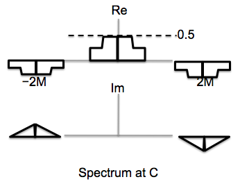
Sketch the real and imaginary parts of Fourier coefficients for signal at point C,
right after we demodulate the combined signal using a sine. The result is passed through
a low-pass filter with a cutoff of M; compare the signal at point E to the two input signals
and summarize your findings.
The signal at point E is a scaled replica of b[n].
Problem .
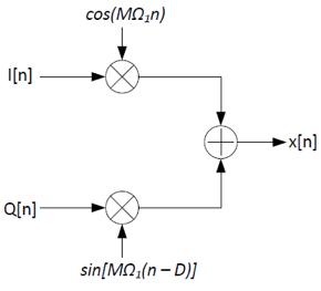
The diagram for a broken IQ transmitter is shown below. Assume N=1024 and M=64.
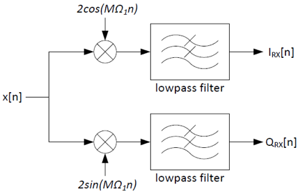
The IQ receiver was designed assuming the transmitter was working correctly:
The broken transmitter sent the symbols I=1 and Q=1. However,
the receiver received the symbols IRX=0.617 and
QRX=0.924. What is the value of D?
x[n]=I[n]cos(MΩ1n) + Q[n]sin(MΩ1n - MΩ1D)
Recall the identity sin(a-b) = sin(a)cos(b) - cos(a)sin(b):
You can use either of the above formulas to solve for D: D = 1.
The broken transmitter sent the symbols I=1 and Q=1. However,
the receiver received the symbols IRX=0 and
QRX=0. What is the value of D?
D = 4.
Problem .
Consider a convolution code with two generator polynomials: G0=101 and G1=110.
What is code rate r and constraint length k for this
code?
We send two parity bits for each message bit, so the code rate r is 1/2.
Three message bits are involved in the computation of the parity bits, so
the constraint length k is 3.
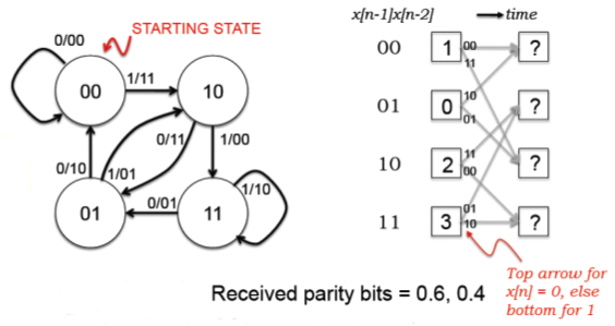
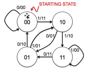
Draw the state transition diagram for a transmitter that uses this
convolutional code. The states should be labeled with the binary string
xn-1...xn-k+1 and the arcs labeled with
xn/p0p1 where x[n] is the
next message bit and p0 and p1 are the
two parity bits computed from G0 and G1 respectively.
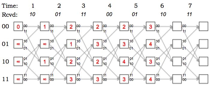
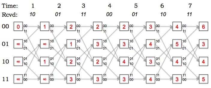
The figure below is a snapshot of the decoding trellis showing a
particular state of a maximum likelihood decoder implemented using the Viterbi
algorithm. The labels in the boxes show the path metrics computed for
each state after receiving the incoming parity bits at
time t. The labels on the arcs show the expected parity bits
for each transition; the actual received bits at each time are shown
above the trellis.
Fill in the path metrics in the empty boxes in the diagram above
(corresponding to the Viterbi calculations for times 6 and 7).
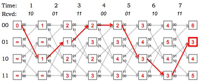
Based on the updated trellis, what is the most-likely final state
of the transmitter? How many errors were detected along the most-likely
path to the most-likely final state?
The most-likely final state is 01, the state with the smallest path metric.
The path metric tells us the total number of errors along the most-likely
path leading to the state. In this example there were 3 errors altogether.
What's the most-likely path through the trellis (i.e., what's the
most-likely sequence of states for the transmitter)? What's the decoded
message?
The most-likely path has been highlighted in red below. The decoded message
can be read off from the state transitions along the most-likely path:
1000110.
Based on your choice of the most-likely path through the trellis,
at what times did the errors occur?
The path metric is incremented for each error along the path. Looking
at the most-likely path we can see that there were single-bit errors
at times 1, 3 and 5.