Integrated Logic Analyzer ILA (Draft - 10/2017)
A physical logic analyzer is simply a digital system that samples
various probes and displays the signal. Since generally not
all the gates are used in a FPGA, why not use parts of the FPGA to
synthesize a logic analyzer? That's exactly an Integrated Logic Analzyer ILA.
The feature of the full feature system edition of Vivado allows
you to view your actual signals in your design with a
synthesized logic analyzer. To view the signals, additional signals
are place and routed but used internally to display the waveforms.
Obviously, to run, your design must synthesize and loaded to the
FPGA.
An ILA Tutorial
Download the following files and create a project
- labkit_lab4.v
- Nexys4DDR_Master_lab4.xdc
- display_8hex.v
Add ILA to your design. Under Project Manager, select IP Catalog.
Expand /Debug & Verification/Debug and add ILA from the catalog.

- For this example, add logic analyzer two probes for debugging.
- Select Native.
- Select the appropriate number
of samples. Caution: the samples uses BRAM on the FPGA and reduces the amount available.
- Capture Control allows storing data based on user parameters.
- Advance Trigger allows selection of events to trigger
the ILA.
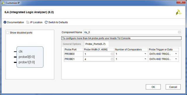
- Do not click OK as this point. Click on Probe_Ports (green arrow) tab will take you to the next screen.

- Logic analyzer probes are created and named. Set probe1 width to 4.
probe0 will be used to display clock.
probe1 will be used to display 4 bits from hcount.

- A ila_0 Verilog module is created. The ports are defined in the module.
  module ila_0 (
            clk,
            probe0,
            probe1
            );

  input clk;
  input [0 : 0] probe0;
  input [3 : 0] probe1;

- In order to view the signals, the logic analyer probes must be defined in
your design. The clock (clk) for ILA is generally the system clock.
Instantiate ila_0 in your labkit_lab4.v
ila_0 myila(.clk(CLK100MHZ),.probe0(clock_25mhz),.probe1(hcount[6:3]));

- Synthesize, implement and generate and load the bitstream to the target.
- To display the waveforms
- select hw_ila_1
- click run or right click with mouse on hw_ila1
- add Trigger Setup if needed.
The waveform can be displayed as digital and/or analog format. Right click to select
waveform type. Important: after an ILA is added, the program device dialog will autodetect both the bitstream and a debug probes file, and only after the fpga is programmed with a debug probes file will the hardware manager show the ILA.


