Integrated Logic Analyzer ILA (Draft)
The feature of the full feature system edition of Vivado allows
you to view your actual signals in your design with a
virtual logic analyzer. To view the signals, additional signals
are place and routed but used internally to display the waveforms.
Obviously, to run, your design must synthesize and loaded to the
FPGA.
Implementing ILA
Add virtual test probes to
your Verilog by inserting (* mark_debug = "true" *) to signals to
be displayed on the logic analyzer.
  (* mark_debug = "true" *) wire [2:0] state;  // virtual test probes for logic analyzer
  (* mark_debug = "true" *) wire driver_door;  // virtual test probes for logic analyzer

   // more Verilog, etc...
   wire [1:0] time_param_selector = switch_sync[5:4];
   wire [3:0] time_value =   switch_sync[3:0];
   wire load_start_timer;
   wire [3:0] count;
- Synthesize your design. After synthesis but before "Run Implementation"
"Open Synthesized Design"

- Select "Setup Debug"

- Additional constraints are added your the xdc file. Save the changes.

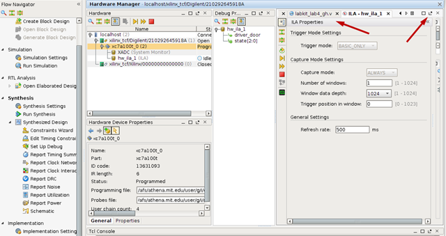
- Run Implementation and load the bit file to the FPGA. An ILA window
will appear. Undock and expand the ILA window. This will
allow you to set up the trigger for the ILA.

- Drag the trigger signal, in this example, driver door (#1) to the Basic
Triiger Setup window (#2).
Select the trigger value from the drop down menu, for
example a 0-1 transisition (#3).
Select the Trigger position (#4). This value
(500) will display 500 samples before the trigger.
Start the capture. (#5)

- In this example, the waveform shows the state value
for the FSM before and after the rising edge of driver_door.

When using the logic analyzer, be sure change the divider clock from
25_000_000 to 3 or 3 clock cyles. Otherwise you will never see any
state changes. You can use a switch to change speeds and avoid recompiling
such as (count == (SW[14] ? 3 : 24_999_999)) count <= 0;
Credit: Ariana Eisenstein


