|
|
|

for 6.111 Introduction to Digital Systems
6.111 home → Labkit home → Programming Methods
Methods for Programming the Labkit
Introduction
The basic ISE tutorial describes how to use the Xilinx ISE software to convert a collection Verilog files into a configuration bitstream (.bit file) for the labkit FPGA. This document describes the three different ways of loading that bitstream into FPGA.
The FPGA used on the labkit is SRAM-based. This means that any design programmed into the FPGA is lost when the power is removed. When the labkit is powered on, the FPGA will attempt to configure itself by loading configuration data from one of a couple sources. If no configuration source is immediately available, the FPGA will wait until a source becomes available. While it is waiting, all of the FPGA's I/O pins are held in tristate, and all of its internal flip-flops are held in reset.
The FPGA configuration data can be loaded from three different sources.
- Configuration bitstreams (
.bitfiles) can be downloaded directly to the FPGA via the labkit's JTAG connector. Configuration data loaded this way will be lost when the labkit is turned off. - The configuration data can be loaded from a compact flash card inserted into the CF socket in the upper right corner of the labkit. Up to eight configurations can be stored on one compact flash card at a time: a switch on the labkit PCB selects which configuration is loaded into the FPGA.
- The configuration data can be stored in an PROM on the labkit PCB. The configuration data will be automatically copied from this PROM to the FPGA each time the labkit is turned on. The PROM itself is programmed through the labkit's JTAG connector.
Configuring the Labkit Using JTAG
Directly configuring the FPGA over JTAG is the fastest way to program the labkit, and is the recommended configuration method when debugging a new design.
- Turn on the labkit.
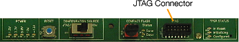
- Connect the short ribbon cable on the end of the Xilinx JTAG adapter ("Parallel Cable IV") to JTAG connector in the upper right corner of the labkit PCB. The status LED on the JTAG adapter should turn from orange to green when the cable is connected to a powered-on labkit. (If the status LED is not illuminated, check the back of the PC to make sure the adapter is correctly attached. The adapter draws power from one of the PC's PS/2 ports: make sure that the PS/2 pass-through adapter is fully seated.)
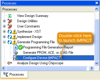
- Launch the iMPACT application. This can be done from within Project.Navigator by double-clicking on the "Configure Device (iMPACT)" task. (You may have to expand the "Generate Programming File" line to see this item.) Alternatively, iMPACT can be launched from the Windows "Start" menu (Start → Programs → Xilinx ISE 8.2i → Accessories → iMPACT).
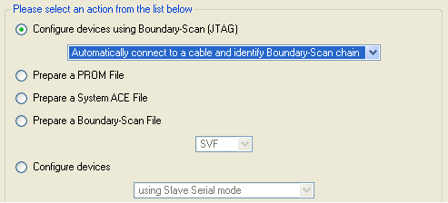
- When iMPACT starts up, a dialog box will ask you what you want to do. Select "Configure devices" and "Automatically connect to cable and identify boundary-scan chain" (the defaults) and click "Finish".
- iMPACT will connect to the JTAG adapter cable, and search the JTAG chain for devices. It should detect three devices on the chain, as shown below.
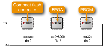
- iMPACT will prompt you to assign a programming file to each of the devices in the chain, in turn. The first device (
xccace) is the compact flash controller chip. Instead of selecting a file for this device, click the bypass button. The second device (xc2v6000) is the FPGA itself. When prompted to select a programming file for this devices, choose thelabkit.bitfile in your project directory. The third device (xcf32p) is the configuration PROM. Bypass this device as well.(When selecting the
labkit.bitfile, iMPACT will warn that the startup clock has been changed to JtagClk. This is harmless.) - Right-click on the picture of the
xc2v6000device and choose "Program..." In the dialog box that appears, make sure the "Verify" option is turned off. Click the "OK" button to start downloading the configuration data to the FPGA. - The programming process should only take a couple of seconds. While the programming process is in progress, the yellow "Initializing" LED in the upper-right corner of the labkit PCB will illuminate. When the process completes (successfully), the yellow LED will go out and the green "Configured" LED will light.
Configuring the Labkit Using a Compact Flash Card
The labkit's compact flash interface is a convenient means of storing mature designs, so that they can be quickly reloaded when desired. Since up to eight configurations can be stored on one compact flash card, this is a good way to keep intermediate versions of a design, or diagnostic programs, available for easy access.
- Launch the iMPACT application. This can be done from within Project.Navigator by double-clicking on the "Generate PROM, ACE or JTAG file" task. (You may have to expand the "Generate Programming File" line to see this item.) Alternatively, iMPACT can be launched from the Windows "Start" menu (Start → Programs → Xilinx ISE 8.2i → Accessories → iMPACT).
- The iMPACT programming tool will launch, and a dialog will ask you what you want to do. Select the option labeled "Prepare a SystemACE file" and click "Next".
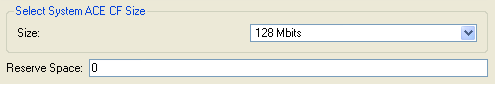
On the next form, the choice of operating mode (novice or expert) is unimportant. On the third form, when asked to specify the size of the CF card, and the amount of space to reserve, just accept the defaults.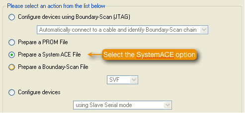
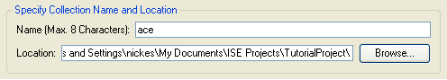
- Choose a name and a location for the SystemACE file collection you are about to generate.
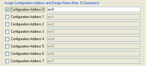
- SystemACE allows up to eight designs to be stored on a single CF card. A switch on the labkit selects which design will be loaded into the FPGA. Check the boxes for as many designs as you want to include on the CF card.
- When the summary screen is displayed, clic "Finish". iMPACT then will begin asking you to add design files (
.bitfiles generated in Project Navigator) for each configuration. You can potentially add more than one design file for each of the up to eight configurations (if there were more than one FPGA on the board, for example), but for the labkits, only add one design per configuration. - Ignore the warnings about changing the configuration clock.
- Once all of the configurations have been specified, right-click anywhere in the upper-right pane of the iMPACT window (with the system diagram) and select "Generate File..." from the pop-up menu.
Click "OK" in the pop-up dialog to generate the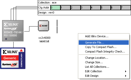
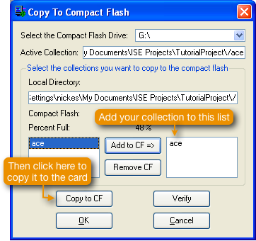
.acefiles. - Make sure your compact flash card is inserted into the reader, then right click again anywhere in the upper-right pane of the iMPACT window and select "Copy to CompactFlash...". Select the collection you just generated and copy it to the CF card.
- Insert the CF card in the labkit. The socket is on the upper right side of the labkit, just below the PCB. The card is inserted upside down.
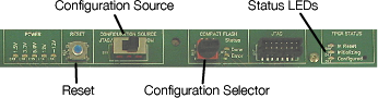
- Make sure the configuration source is set to "JTAG/CF", and select the configuration selector switch to the appropriate number.
- Power on the labkit. The green SystemACE status LED should blink for a couple seconds, and then come on steady, indicating that the FPGA has been configured. At the same time, the green FPGA status LED labeled "Configured" should turn on.
When you use iMPACT to copy design files to a compact flash card, it will not overwrite any designs already on the card, but it does overwrite the xilinx.sys file in the card's root directory. The labkit uses this file to locate the .ace design files on the card, so the labkit will not be able to access the older designs, once xilinx.sys has been overwritten.
Despite its .sys extension, xilinx.sys is actually a simple text file that you can edit in Notepad, or any other text file editor. The format is pretty self-explanatory, and is defined in the datasheet for the SystemACE controller chip. It is a simple matter to manually copy the .ace files generated by iMPACT to your compact flash card, and then manually add entries for them in the xilinx.sys file.
Note that iMPACT actually generates two xilinx.sys files on a compact flash card: one in the root directory, and one in the directory where the individual design directories are located. Only the xilinx.sys file in the root directory is read by the labkit.
The compact flash interface chip on the labkit is relatively simplistic, and poses a number of restrictions on the formatting of the compact flash card.
- The compact flash card must be formatted as DOS FAT12 or FAT16.
- All directories accessed by labkit must have 8.3-format names.
- The master boot record for the compact flash card must specify only one reserved sector
- The compact flash card must be formatted with a sector-per-cluster size of more than one. (That is, the sector size must be greater than 512 bytes.)
- The root directory cannot contain more than 16 files or directories, including deleted files and directories.
That last restriction is particularly annoying, so be careful not to create unnecessary files or directories in the root directory of your compact flash card. If your card suddenly stops working in the labkit (the red "Error" LED comes on steady), it probably means you violated this 16-file/directory limit, and you must now reformat the card.
If you reformat a card in Windows, be sure to choose the FAT16 format (i.e., "FAT", not "FAT32"). Also, note that Windows does not always choose to format a card with a sector-per-cluster size of more than one, as required by the labkit. The best way to format a card is with the mkdosfs program (which should already be installed on any x86 Linux system, and is also available for Windows). The following command line should produce the correct format for a 128MB card on drive G:
mkdosfs -v -F 16 -R 1 -s 4 g:
mkdosfs is not installed on the lab computers, so you will have to do this using your own machine.
Configuring the Labkit using the PROM
The labkit contains a PROM chip that can be used to store one configuration file. The stored configuration file will be loaded into the FPGA when the labkit is turned on. To program a configuration file into the PROM, follow the steps below.
- Launch the iMPACT application. This can be done from within Project.Navigator by double-clicking on the "Generate PROM, ACE or JTAG file" task. (You may have to expand the "Generate Programming File" line to see this item.) Alternatively, iMPACT can be launched from the Windows "Start" menu (Start → Programs → Xilinx ISE 8.2i → Accessories → iMPACT).
- The iMPACT programming tool will launch, and a wizard will ask you several questions about what you want to do. Select "Prepare a PROM file" in the first dialog.
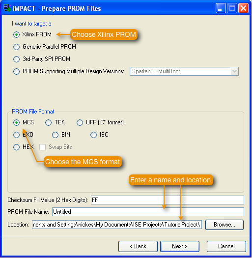
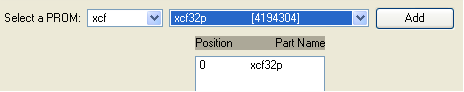
- In the next dialog, select "Xilinx Serial PROM" as the target, and "MCS" as the file format, and enter a name and location for the PROM file, as shown below. Then click "Next".
- In the next dialog, select an XCF32P PROM device, and click the "Add" button. Then click "Next", and finally "Finish".
- Click "OK" on the "Add Device" dialog to beginning adding configuration files to the PROM. Then select the
.bitfile for your design. - When asked if you want to add any additional files to the data stream, choose no. Then click "OK".
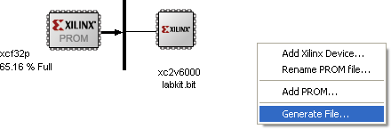
- Right-click anywhere in the upper-right pane of the iMPACT window and select "Generate File..." from the pop-up menu.
- Once the PROM file is generated, turn on the labkit and connect the Xilinx JTAG cable, as described above for configuring the labkit via JTAG.
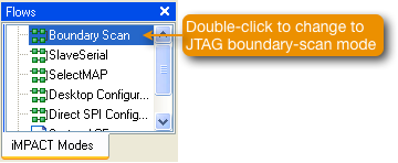
- Double-click on the "Boundary Scan" item in the "Flows" pane of the iMPACT window, to switch iMPACT to JTAG programming mode.
- Right-click in the iMPACT window and select "Initialize Chain". iMPACT should detect three devices on the JTAG chain.
- iMPACT will prompt you to assign configuration files to each of the three devices. Bypass the first two devices, and select the
.mcsPROM file that you just generated for the third device (thexcf32p). - Right-click on the
xcf32pdevice and select "Program...".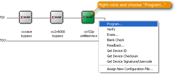
- Make sure the "Erase before programming" and "Verify" items are selected, and click "OK".
- It will take several minutes to program the PROM.
- After the PROM has been successfully programmed and verified, set the configuration selector switch on the labkit to the PROM setting. Also, remove any compact flash card from the labkit. Then, power-cycle the labkit. (Pushing the labkit's reset button does not trigger a reconfiguration from the PROM: it is necessary to power-cycle the kit to reload the FPGA from the PROM.)
- It will take several seconds for the FPGA to configure itself from the PROM. Once it does, the green "Configured" LED on the labkit will illuminate.
MIT 6.111 Introduction to Digital Systems, Updated February 07, 2007