The input decks for this problem can be found in the test suite as leifer1.inp and leifer2.inp. It was first devised by J. Leifer in 2003. The structure is a thin square sheet with an edge length of 229 mm and a thickness of 0.0762 mm. It is fixed on one side and moved parallel to this side on the opposite side by 1 mm. Young's modulus and Poisson's coefficient are 3790 MPa and 0.38, respectively. Experimental evidence points to the creation of wrinkles due to this shear deformation.
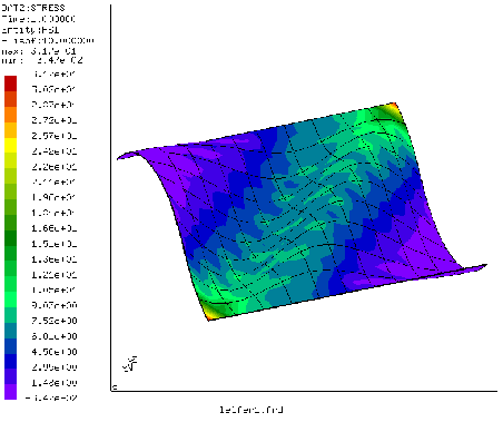
Here, two approaches are described to simulate this experiment. In both cases the sheet is simulated using quadratic shell elements. In the first simulation (leifer1) the material is considered as a linear elastic isotropic material, and wrinkling occurs due to natural buckling processes in the sheet. To enhance this buckling, the coordinates in the direction perpendicular to the sheet (this is the z-direction in our simulation) are slightly perturbed in a aleatoric way (look at the coordinates in the input deck to verify this). Furthermore, the simulation is performed in a dynamic procedure starting with very small time steps. Figure 49 shows the maximum principal stress in the deformed sheet (the edge at x=0 was fixed, the edge at x=229 was moved 1 mm in negative y-direction). One nicely notices the wrinkles. A look at the smallest principal stress shows that there are virtually no pressure stresses in the sheet: they were removed by buckling. A disadvantage of this kind of simulation is the very long computational time (336 increments for a step time of 1!).
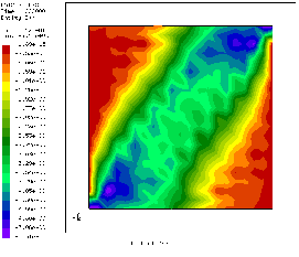
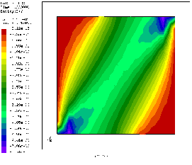
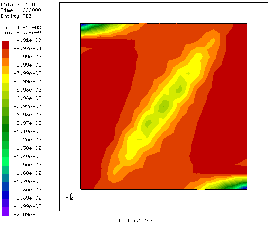
The absence of pressure stress points to a second way of obtaining the correct stress distribution: instead of simulating the material as isotropic, one can use a tension-only material model (leifer2). This has the advantage that convergence is much faster (small computational times). Figures 50 and 51 compare the shear stress of both simulations: they match quite nicely (the shear stress distribution in an isotropic simulation without wrinkling is totally different). The same applies to the other stress components. The use of a tension-only material, however, does not lead to out-of-plane deformations. Here, wrinkling can only be derived indirectly by looking at the smallest principal strain (Figure 52). The large negative values point to the existence of wrinkles.