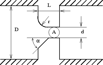
The geometry of the orifice fluid section is shown in Figure 76. It is characterized by the following constants (to be specified in that order on the line beneath the *FLUID SECTION card):
Depending on the orifice geometry, an inlet corner radius or an inlet corner angle (chamfered inlet) should be selected. They are mutually exclusive. The corrections for a chamfered inlet are taken from [27].
The last constant, i.e. the number of a reference network element, is necessary in case a rotating structure is preceded by a network element which diverts the upstream air velocity from the axial direction (such as a preswirl nozzle). In that case, the rotational velocity of the orifice has to be corrected by the circumferential component of the velocity at the exit of the preceding element.
The calculation of the discharge coefficient ![]() can be performed according
to different formulas. This is selected by the TYPE parameter:
can be performed according
to different formulas. This is selected by the TYPE parameter:
Example files: linearnet, vortex1.