The Challenge: Text Goes Here
Technical Approach: Text Goes Here
Selected Design Features: Text Goes Here
 |
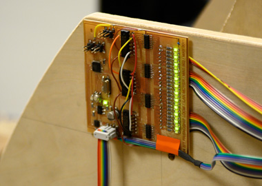 |
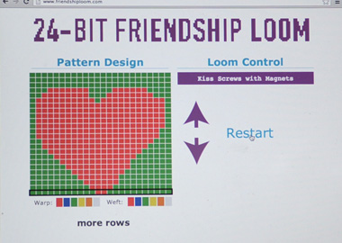
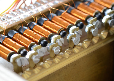
| A browser-based interface allows the user to design patterns and interact with the loom. | The loom's 24 electromagnets are energized by a Gestalt-based control board. |
 |
 |
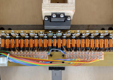
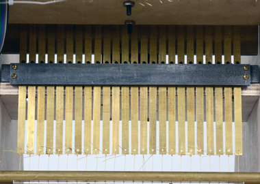
| The electromagnets are mounted on a slider that is retracted once the magnets are energized. | Flexures become attached to and pulled back with the active electromagnets. |
 |
 |
| Screw-heads on the unattached flexures are in the path of a lift knife. | The lift knife pulls up any flexures that were not selected and retracted by the electromagnets. |
 |
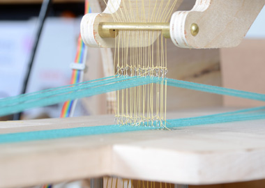 |
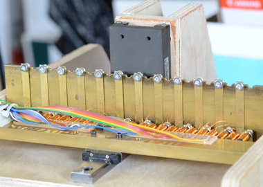
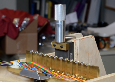
| Control cables are connected to the bottoms of the flexures. When a flexure is lifted, so is the cable. | Each control cable ends in a loop through which one of the warp threads passes. The lifted threads create a shed for weaving. |
 |
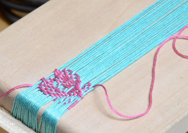 |
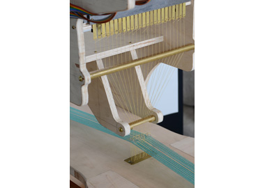
| A weight box maintains constant tension on the control cables so that they stay straight. | The beginnings of a friendship bracelet! |
 |
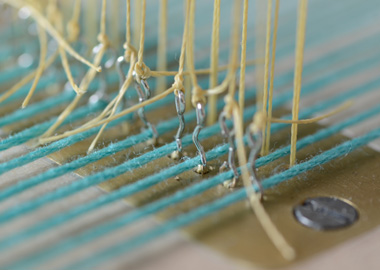 |
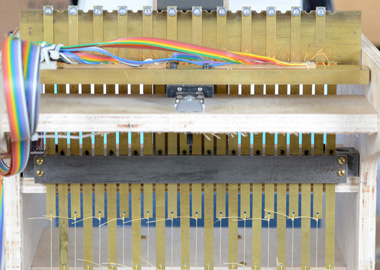
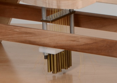
| The pitch of the control threads is reduced significantly between the flexures and the shed. | Each steel loop is biased against a brass baseplate by a second set of cables going into the weight box. |
 |
 |
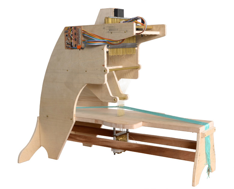
| The flexures are constrained by a steel guide. Pins in each flexure keep it from falling thru the guide. | A set of handles let's the user manually actuate the two sliding mechanisms of the loom: the electromagnet slider and the lift knife. |
 |
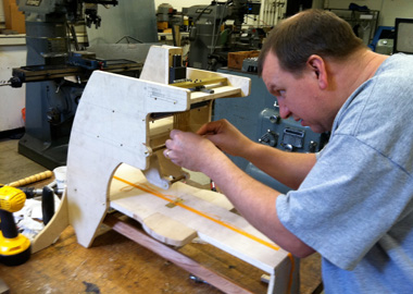 |
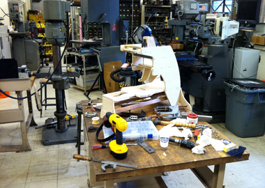
| Much of the loom was constructed at the Edgerton Student Shop. | Many thanks to Mark Belanger, the Edgerton Student Shop's manager, for all of his help! |
 |
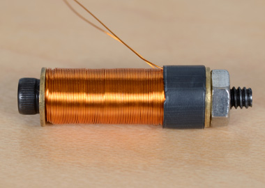 |
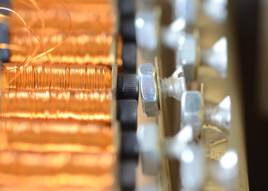
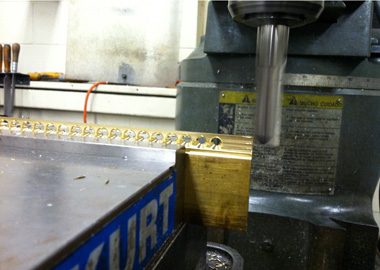
| The features of the knife that engage with the flexure screw-heads were created by removing the top of a row of countersunk holes. | All 24 electromagnetic coils needed to be very consistent to achieve maximum system efficiency. |
 |
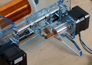 |
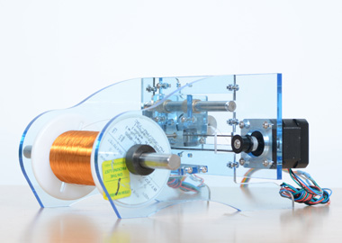
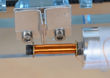
| A coil-winder was built to precisely wind each of the electromagnets. | Magnet wire passes through a moving aperture and is wound up on a spinning core. |
 |
|
| A close-up of the winding process. |