Description
This project is a continuation of the robotic gripper I designed for the MIT Class 6.142 to attempt to make a simple device that can grasp complex shaped objects and apply a torque to them. For a (very) detailed look at this work you can download my undergraduate thesis on my publications page, or look at the first iteration of this project here .
This is an overview of a robotic gripper developed in order to facilitate the construction of furniture by a team of mobile Kuka Youbot robots. The key feature of the gripper are that it is capable of applying a torque exceeding 3nm to almost any irregularly shaped object up to 100mm in diameter. Also the gripper is designed to be lightweight and to be compatible with tool changing systems - one of which was designed and implemented for a research project at MIT CSAIL that aims to have small industrial robots assemble furniture.
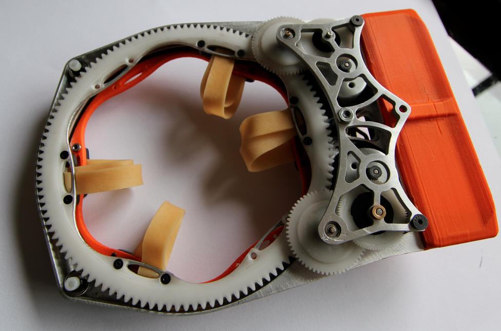
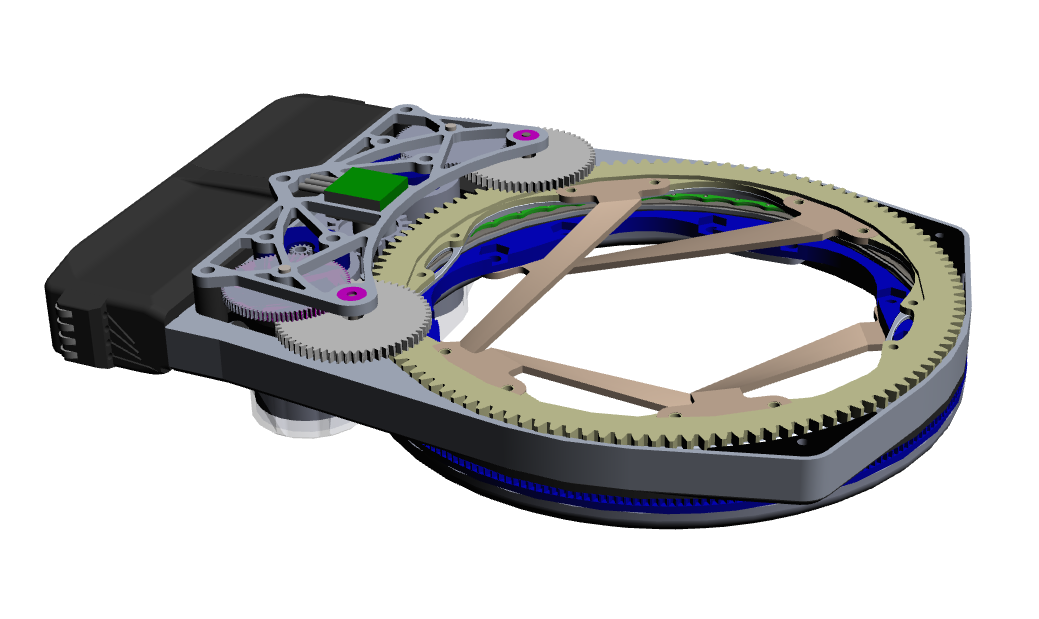
The above two images show the final gripper as both a rendered solid model (top), as well as a photograph (bottom).
The Gripper works by using elastic elements which have both ends connect to movable rings, which enables the device to easily rotate the part after it has been grasped. The gripper functions by the encirclement of the target object with flexible elastic members. These members are attached to two separate rings (As shown in the images above). The top ring is driven by a pair of motors, whereas the bottom ring is un-actuated. The unactuated ring contains a set of magnets designed to increase the ringŐs dynamic friction. As the driven ring is spun by the motors, the elastic elements begin to contract around the object in the center as can be seen in the diagram below. After a threshold torque is reached, the bottom ring and the object begin to spin as well. This design enables the rings to maintain an approximately constant gripping force on the part. The gripping strength is controlled by the combination of the elasticity of the cables and the force exerted by the magnets. Elasticity permits the tool to be non-destructive in its application of force, and this force is distributed almost uniformly around the circumference of the object. Additionally, the elastic nature of the force application permits considerable error in position and orientation while remaining operational.

A series of frames show the gripper gripping and spinning an object.
More information about the design and the project can be found in my thesis here . Following are a few more pictures giving a glimpse of the grippers design and uses.
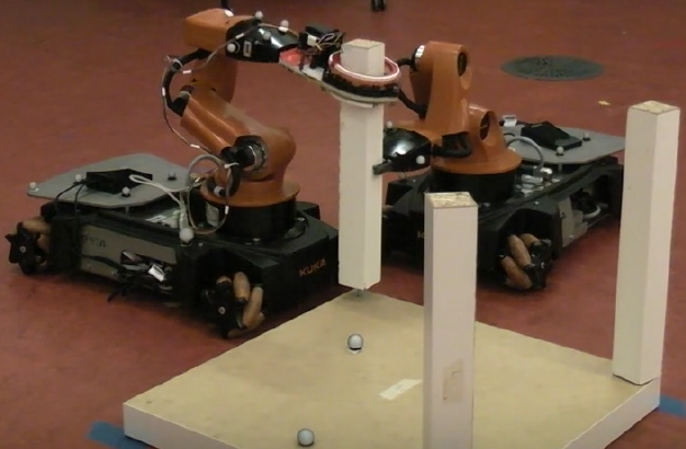
This shows the older version of the claw attaching one of the table legs to the Ikea Table. Notice how the second robot has to hold the leg while the gripper attaches the leg. This shows one of the limitations of the gripper - that it is not able to pick up objects that do not provide a location to grab onto.
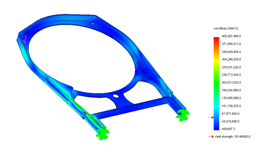
This shows some of the FEA (finite element analysis) work that went into designing the unibody frame for the gripper. The solidworks add on allows simulated forces to be applied to bodies in order to identify weak locations in the design.
|
Videos and 3D Models This video shows the claw attached to a Kuka you-bot trying to screw in the table legs on a small table from IKEA. This claw is ideal for this task because it can apply a torque to objects of nearly any shape or surface properties, as well as applying this torque with high degrees of both linear and rotational misalignment. This video shows how the claw can manipulate very delicate objects - in this case the focus adjustment on my camera Lens This is supposed to be a 3d-pdf model of the gripper but we seem to be having technical difficulties at the moment |