Motor Velocity Controller : In this lab, I designed a PI controller to do closed-loop velocity control on this DC motor. The lab began with only implementing proportional control, and had us realize the elimination of steady-state error in a real system by adding the integral control after.
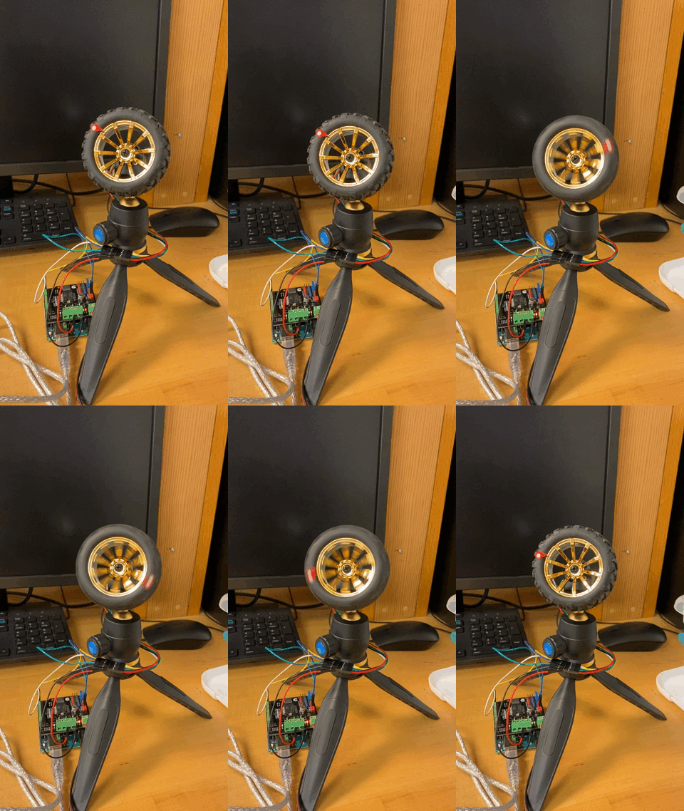
Active Gimbal Control : After modeling the DC motor plant as a second-order system and then making a simulation of the closed loop system in Simulink, we controlled the system with a PD controller to make it well-damped, increasing the system's stability to adequate gimbal standards. We then modeled the motion of the spring-mass system and set the gimbal-camera system to the same frequency so as to track the mass while it moved, as seen in the video
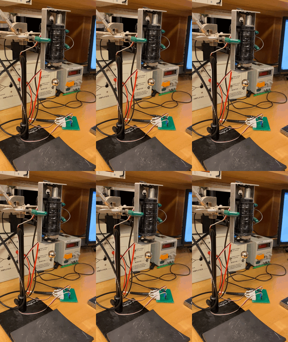
Magnetic Levitation : Here we modeled the amount of magnetic force needed to just hold the ball in the air then controlled the current according to the distance the ball was from the sensors. For this lab we were given the option of designing a PID or PD controller in sisotool to levitate the magnet, and my group found that the overshoot using a PID design was too high for the system to be reliably stable. We then managed to set the current as a sine wave with an amplitude of 0.1 at 1Hz and levitate the ball up and down for more than 20 seconds.
Two-Wheeled Self-Balancing Robot Control : Modeling our system as an inverted pendulum on a moving cart, we designed a PID controller to stabilize the measured angle of tilt the robot was experiencing by having the robot move backwards and forwards accordingly. Our final controller that we designed in Sisotool had a settling time of less than 1 second and a damping ratio greater than 0.7, which allowed our robot to stay standing for more than 15 minutes.
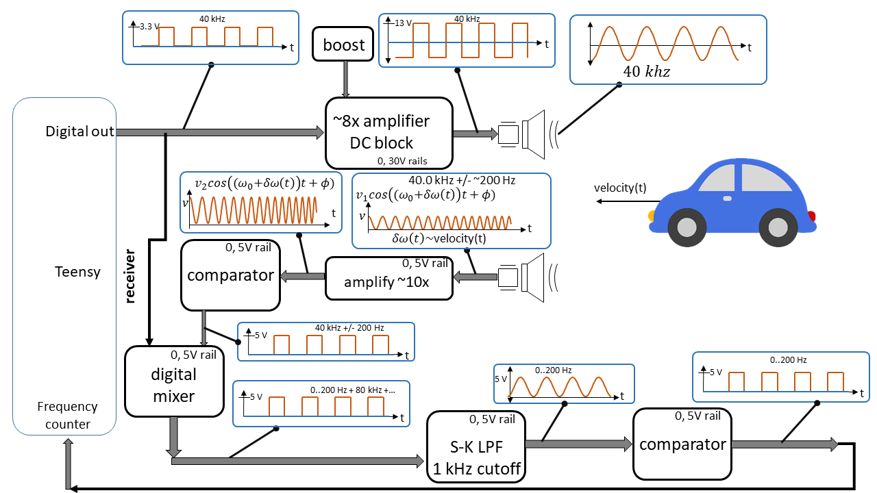
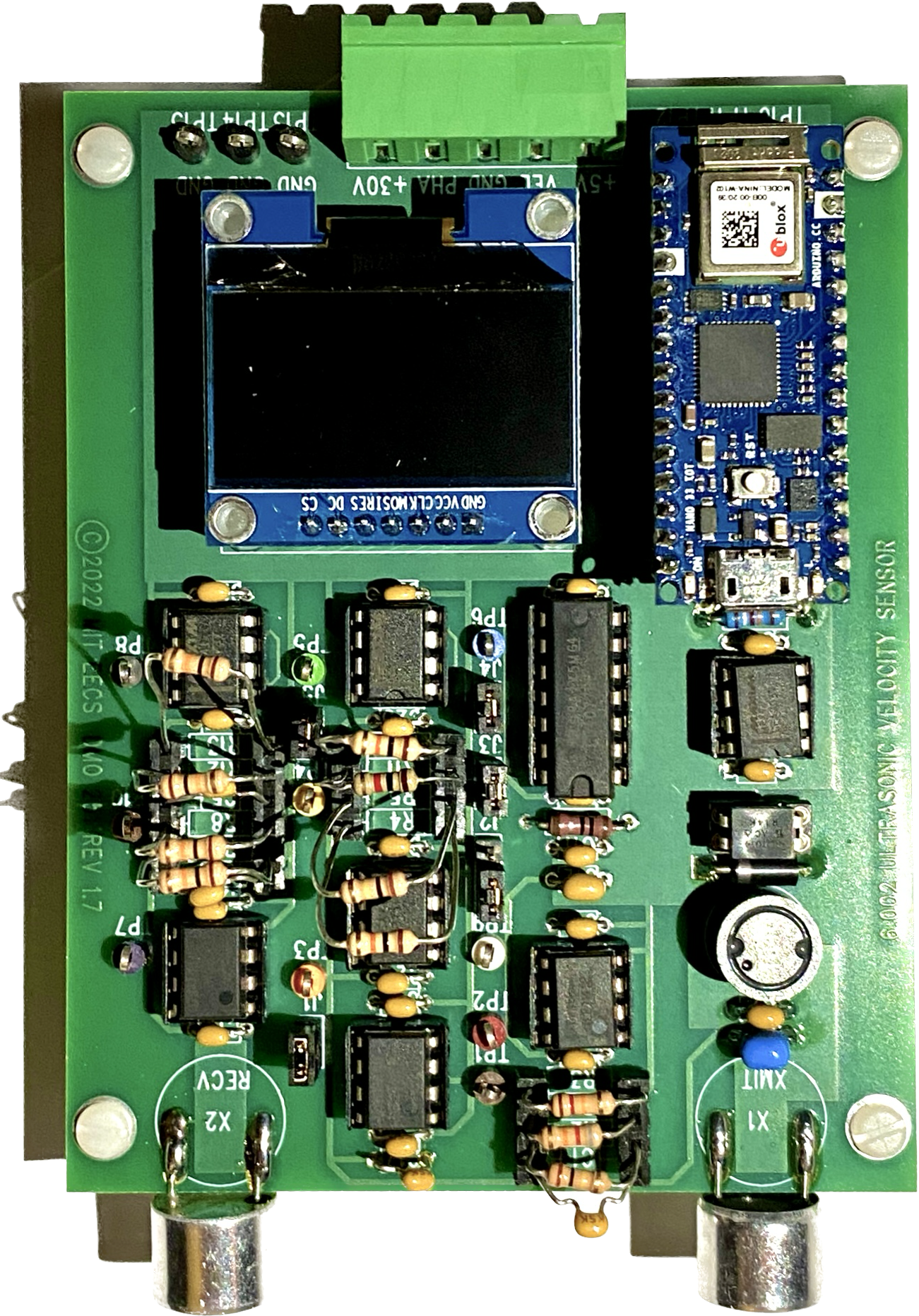
Over the course of the semester, each student designed and built an ultrasonic velocity sensor with the stages pictured on the left. For each stage, I calculated the required resistance/capacitance needed and chose components accordingly, then measured that stage's function with an oscilloscope and power supply to ensure it performed the intended behavior.
In order: first we create a square wave with the Arduino Teensy then amplify it with an amplifier. The ultrasound wave frequency changes slightly when bounced off of a moving object and is recieved then amplified by 10x for us to determine the frequency discrepency from the original. To do this, we turn the signal into a square wave (because we only need the frequency) then multiply the recieved and original square waves with an XNOR gate. Using a 1kHz Sallen-Key low-pass filter, we remove the resulting 80 kHz signal and are left with the doppler shift frequency that we want, which is proportional to the velocity of the moving object. Additionally, since we only used the 5V powering the Teensy, we created a 30V supply voltage from those 5V with a boost converter.
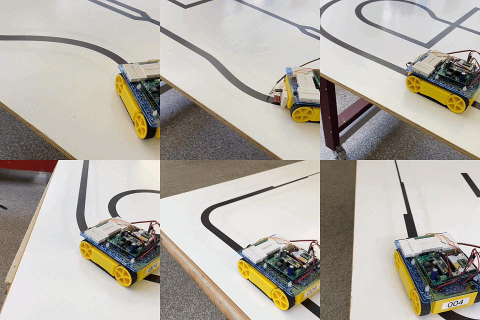
This class consisted of many short labs, culminating with a two-week long project to control a robot to follow an intricate line track. My partner and I used three color sensors positioned in the middle of the front of the robot to detect the black line against the white background. We then programmed the Arduino Uno to set the motors' speeds proportional to how great of a difference that side's sensors saw in white and black (since the sensors did not pick up boolean values and this way we could detect when the center of the robot was just starting to leave the line.) We used the central sensor to determine if we were at a sharp corner, where all three sensors would suddenly read only white. In this case, we set the robot to spin in the direction it last detected the greatest difference after a small amount of time until it reached a line again.