Contents
 Intro
IntroWhat study to use
Material properties
Boundary Conditions
Loads
Mesh
Interpreting Results
Intro
Finite Element Analysis is a powerful tool for analyzing structures before fabrication. FEA works by dividing up a structure into small elements, and through constitutive relationships, finding the response of a system to an external input. FEA can be quite fast as long as the appropriate model is being applied.
What study to use
First the desired analyis must be chosen. Is the system linear or nonlinear? If it is nonlinear, is it force controlled or displacement controlled? Large strain or small strain? Time-dependent (e.g. viscoelastic dynamics)? What solution algorithm do you use? Can this system be approximated by a 2D system (plane stress, plane strain, or axisymmetric)? I recommend taking a course-to-fine approach: make a simple model that captures most of the appropriate physics, then as you get closer to the final design, gradually make the model more complex to capture more detail.
Material properties
The material properties are essential to getting accurate results. Get the appropriate material properties from a reputable source like MatWeb, or from experimental results. Default SolidWorks material properties may be insufficient for your analysis. You may need to put in material constants, or curves for stress-strain or fatigue. Also choose the appropriate model for the material (linear elastic, anisotropic, etc.)
Boundary Conditions
The right boundary conditions are also important. Always be wary of what is "fixed." Consider bolted joints, pin joints, bearings, friction, elastic foundation, fixed, roller-slider, and contact conditions (bonded, no penetration, etc.) Also, be careful about using symmetry. For example, symmetry should not be used in dynamic simulations because the symmetry changes the mass distribution.
Loads
Consider what the loads are and how/where they are applied. Is it a remote load? Pressure or force? What order are the loads being applied (is the load on a deformed or undeformed shape?) Is the force conservative or non-conservative (does it stay in the same direction or does it follow the structure?) Also, for thermal loads, be careful in calculating the convection coefficient.
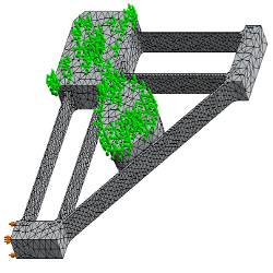
Mesh
Once all of the above has been addressed, then one can worry about mesh size. The mesh size presents a trade-off between speed and accuracy. A course mesh is faster, but less accurate. A fine mesh is more accurate, but much slower. Thus, the mesh should gradually be made finer until it converges on a solution in a reasonable amount of time. Adaptive methods can be used for mesh convergence (see SolidWorks tutorials on h-adaptive and p-adaptive methods). There are also approximations that can be made to mesh element types, for example, beam or shell elements.
Interpreting results
There are many cool ways to understand what is happening to the structure. Consider animations, contour lines, plotting the deformed shape over the original shape, and design insight.