Spiral Sensor Array
To monitor changing conditions like temperature, conductivity, and dissolved particle concentration, it is more effective to use an array of anchored sensors than send mobile robots to take survey measurements. In that form, one can see the flux of these conditions, how they change over time and space. Another advantage is that mobile robots don not have to keep going out to measure the same things, at least around one area of the vent field. It also allows a comparison of the conditions in many places at one point of time, giving a better idea of the overall condition distribution.
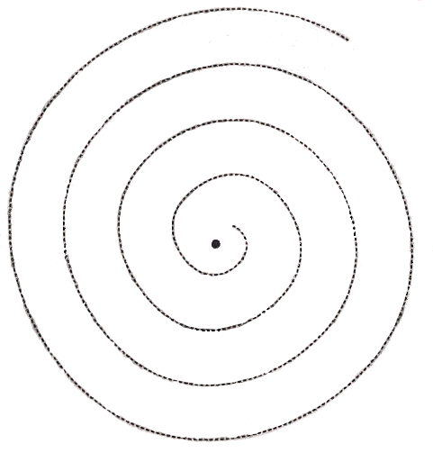
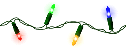
The area of most interest is near the vents, so the concentration of sensors near the vent should be higher and get lower as the distance from the vent increases. To accomplish this, the Sensor Array will be arranged in a spiral pattern. This approach will also simplify deployment, because the sensors will all be spaced on a cable , much like a string of Christmas lights (see bottom of the page). The Manned Vehicle can bring the conglomeration out there and the ROV Tug can lay them out with precision, selecting the best placement.
The end of the string farthest from the vents will connect to a docking station. The Docking Station is connected by cable to the Habitat. Both the spiral string cable and the DDS cable back function for communications and power. Hence, the Sensor Array data can be transferred back to the Habitat continuously, and the sensors will have the power to run without the problems of recharging batteries.

The Spiral cable, since permanent, will be negatively buoyant. The evenly spaced individual sensor packets, called Sensor Buoys, will be slightly positively buoyant. They will not lift the cable, but will be free floating at a uniform height to attain better readings.
The Spiral Sensor Array will be deployed after basic mapping and condition distribution maps are completed. Based on the information gathered in the AUV survey missions, the scientists will decide how close to the vent the spiral goes to keep the cable, which can withstand up to about 400 degrees Celsius from melting. They will also decide what sensors will be included on the sensor buoys for optimum effectiveness. The sensors will include temperature and salinity sensors, but the utility of other ones is up to them. See sensors to take a look at some of the possibilities. They will also decide how many sensors are necessary, depending on the rate of condition changes around the vent, probably between 40-100 individual sensor buoys.
Technical Specifications
The design for these sensor buoys will be pretty standard. They would consist of a freely flooded titanium, nickel base alloy structure, to which the sensor components are attached. Flotation material(syntactic foam) will be added to the top of the structure for buoyancy, and also for stability of the structure. The most likely sensors will be a CTD, pH meter, and flow injection analysis to study the composition of the water. The power requirement of each buoy will be low, in the order of 25 watts.
The information will be sent to the Habitat via optical fibers.
References
1. "Distributed Surveillance Sensor Network" www.spawar.navy.mil/robots/pubs/dssn.pdf
2. Picture of Spiral www.miamisci.org/hurricane/
windmove.html
3. Picture of Christmas Lights: http://www.annien.com/Holidays/Christmas/TipsnTricks/String_Lights.GIF


