|
|
|
| Thermodynamics and Propulsion | |
|
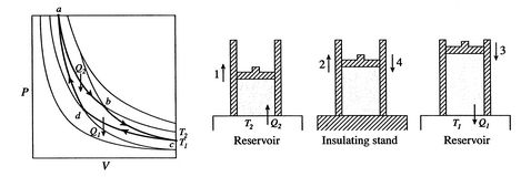
Next: 3.4 Refrigerators and Heat Up: 3. The First Law Previous: 3.2 Generalized Representation of Contents Index 3.3 The Carnot CycleA Carnot cycle is shown in Figure 3.4. It has four processes. There are two adiabatic reversible legs and two isothermal reversible legs. We can construct a Carnot cycle with many different systems, but the concepts can be shown using a familiar working fluid, the ideal gas. The system can be regarded as a chamber enclosed by a piston and filled with this ideal gas.
The four processes in the Carnot cycle are:
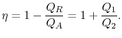
The thermal efficiency of the cycle is given by the definition
In this equation, there is a sign convention implied. The quantities
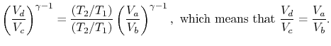
The efficiency can now be written in terms of the volumes at the different states as
The path from states
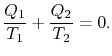
Comparing the expression for thermal efficiency Eq. (3.4) with Eq. (3.5) shows two consequences. First, the heats received and rejected are related to the temperatures of the isothermal parts of the cycle by
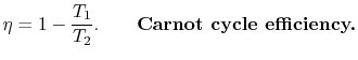
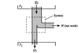
Second, the efficiency of a Carnot cycle is given compactly by The efficiency can be 100% only if the temperature at which the heat is rejected is zero. The heat and work transfers to and from the system are shown schematically in Figure 3.5.
Since
In the Carnot cycle, why are we only dealing with volume changes and not pressure changes on the adiabats and isotherms? (MP 3.3) Is there a physical application for the Carnot cycle? Can we design a Carnot engine for a propulsion device? (MP 3.4) How do we know which cycles to use as models for real processes? (MP 3.5)
Next: 3.4 Refrigerators and Heat Up: 3. The First Law Previous: 3.2 Generalized Representation of Contents Index |
![$\displaystyle \eta = 1+ \frac{T_1[\ln(V_d /V_c)]}{T_2[\ln(V_b /V_a)]}.$](img355.png)