Subsections
3.5 The Internal combustion engine (Otto Cycle)
[VW, S & B: 9.13]
The Otto cycle is a set of processes used by spark ignition internal
combustion engines (2-stroke or 4-stroke cycles). These engines a)
ingest a mixture of fuel and air, b) compress it, c) cause it to
react, thus effectively adding heat through converting chemical
energy into thermal energy, d) expand the combustion products, and
then e) eject the combustion products and replace them with a new
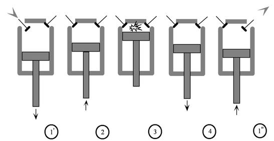
charge of fuel and air. The different processes are shown in
Figure 3.8:
- Intake stroke, gasoline vapor and air drawn into engine (
 ).
).
- Compression stroke,
 ,
,  increase (
 ).
).
- Combustion (spark), short time, essentially constant volume (
 ). Model: heat
absorbed from a series of reservoirs at temperatures
). Model: heat
absorbed from a series of reservoirs at temperatures  to
to  .
.
- Power stroke: expansion (
 ).
).
- Valve exhaust: valve opens, gas escapes.
- (
 ) Model: rejection of heat to series of
reservoirs at temperatures
) Model: rejection of heat to series of
reservoirs at temperatures  to
to  .
.
- Exhaust stroke, piston pushes remaining combustion products out of chamber
(
 ).
).
We model the processes as all acting on a fixed mass of air
contained in a piston-cylinder arrangement, as shown in
Figure 3.10.
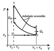
Figure 3.8:
The ideal Otto cycle
|
|
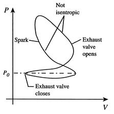
Figure 3.9:
Sketch of an actual Otto cycle
|
|
Figure 3.10:
Piston and valves in a four-stroke internal combustion engine
|
|
The actual cycle does not have the sharp transitions between the
different processes that the ideal cycle has, and might be as
sketched in Figure 3.9.
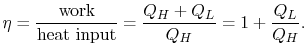
3.5.1 Efficiency of an ideal Otto cycle
The starting point is the general expression for the thermal
efficiency of a cycle:
The convention, as previously, is that heat exchange is positive if
heat is flowing into the system or engine, so  is negative. The
heat absorbed occurs during combustion when the spark occurs,
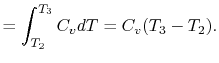
roughly at constant volume. The heat absorbed can be related to the
temperature change from state 2 to state 3 as:
is negative. The
heat absorbed occurs during combustion when the spark occurs,
roughly at constant volume. The heat absorbed can be related to the
temperature change from state 2 to state 3 as:
The heat rejected is given by (for a perfect gas with constant
specific heats)
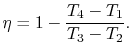
Substituting the expressions for the heat absorbed and rejected in
the expression for thermal efficiency yields
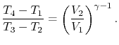
We can simplify the above expression using the fact that the
processes from 1 to 2 and from 3 to 4 are isentropic:
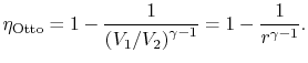
The quantity
 is called the compression ratio. In terms
of compression ratio, the efficiency of an ideal Otto cycle is:
is called the compression ratio. In terms
of compression ratio, the efficiency of an ideal Otto cycle is:
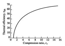
Figure 3.11:
Ideal Otto cycle thermal
efficiency
|
|
The ideal Otto cycle efficiency is shown as a function of the
compression ratio in
Figure 3.11. As the
compression ratio,  , increases,
 increases,
but so does
. If
is too high, the mixture will ignite
without a spark (at the wrong location in the cycle).
increases,
but so does
. If
is too high, the mixture will ignite
without a spark (at the wrong location in the cycle).
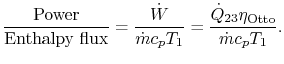
3.5.2 Engine work, rate of work per unit enthalpy flux
The non-dimensional ratio of work done (the power) to the enthalpy
flux through the engine is given by
There is
often a desire to increase this quantity, because it means a smaller
engine for the same power. The heat input is given by
where
-
 is the heat of reaction,
i.e. the chemical energy liberated per unit mass of fuel,
is the heat of reaction,
i.e. the chemical energy liberated per unit mass of fuel,
-
 is the fuel mass flow rate.
The non-dimensional power is
The quantities in this equation, evaluated at stoichiometric
conditions are:
Muddy Points
How is
calculated?
(MP 3.6)
What are ``stoichiometric conditions?''
(MP 3.7)
UnifiedTP
|

![$\displaystyle \frac{\dot{W}}{\dot{m}c_pT_1}=\frac{\dot{m}_\textrm{fuel}}{\dot{m}}
\frac{\Delta h_\textrm{fuel}}{c_p T_1}\left[1-\frac{1}{r^{\gamma-1}}\right].$](img392.png)


![$\displaystyle \approx 9\left[1-\frac{1}{r^{\gamma-1}}\right].$](img398.png)