VI. Rocket Nozzles: Connection of Flow to Geometry
We have considered the overall performance of a rocket and seen that is directly
dependent on the exit velocity of the propellant. Further, we have used the
steady flow energy equation to determine the exhaust velocity using the combustion
chamber conditions and the nozzle exit pressure. In this brief section, we
will apply concepts from thermodynamics and fluids to relate geometrical (design)
parameters for a rocket nozzle to the exhaust velocity.
We will make the following assumptions:
A.
Quasi-one-dimensional compressible flow in a variable area duct
| p = rRT |
(ideal gas) |
 |
(isentropic flow) |
 |
(energy equation) |
imply that
Then from conservation of mass
The above equation relates the flow area, the mass flow, the Mach number
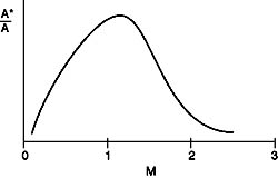
and the stagnation conditions. It is frequently rewritten in a non-dimensional
form by dividing through by the value at M=1 (where the area at M=1 is A*):
which takes a form something like that shown in Figure 6.1 below
Figure 6.1 General form of
relationship between flow area and Mach number.
See this interactively at NASA Glenn
- GO!
|
B. Thrust in Terms of Nozzle Geometry
We can use these equations to rewrite our expression for rocket thrust in
terms of nozzle geometry (throat area = A*, and exit area Ae).
 evaluate at M = 1 (throat)
We can now specify geometry (A* and Ae) to determine Me.
Then use Me with the combustion chamber conditions to determine
thrust and Isp.


Interested in seeing the different types
of nozzles out there? - GO!
|