|
|
|
| Thermodynamics and Propulsion | |
|
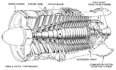
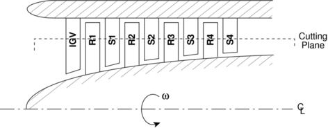
Next: 12.5 Velocity Triangles for Up: 12. Energy Exchange with Previous: 12.3 The Euler Turbine Contents Index 12.4 Multistage Axial CompressorsAn axial compressor is typically made up of many alternating rows of rotating and stationary blades called rotors and stators, respectively, as shown in Figures 12.3 and 12.4. The first stationary row (which comes in front of the rotor) is typically called the inlet guide vanes or IGV. Each successive rotor-stator pair is called a compressor stage. Hence compressors with many blade rows are termed multistage compressors.
One
way to understand the workings of a compressor is to consider energy
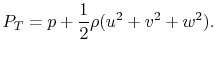
exchanges. We can get an approximate picture of this using the
Bernoulli Equation, where
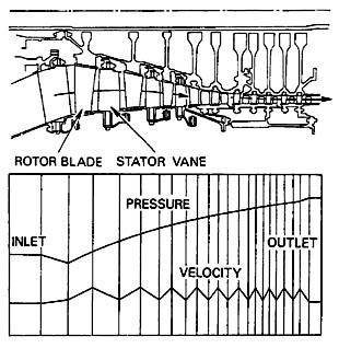
The rotor adds swirl to the flow, thus increasing the total energy carried in the flow by increasing the angular momentum (adding to the kinetic energy associated with the tangential or swirl velocity, The stator removes swirl from the flow, but it is not a moving blade row and thus cannot add any net energy to the flow. Rather, the stator rather converts the kinetic energy associated with swirl to internal energy (raising the static pressure of the flow). Thus typical velocity and pressure profiles through a multistage axial compressor look like those shown in Figure 12.5.
Note that the IGV also adds no energy to the flow. It is designed to add swirl in the direction of rotor motion to lower the Mach number of the flow relative to the rotor blades, and thus improve the aerodynamic performance of the rotor.
Next: 12.5 Velocity Triangles for Up: 12. Energy Exchange with Previous: 12.3 The Euler Turbine Contents Index |