|
|
|
| Thermodynamics and Propulsion | |
|
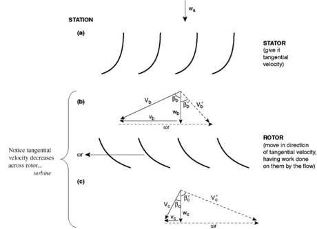
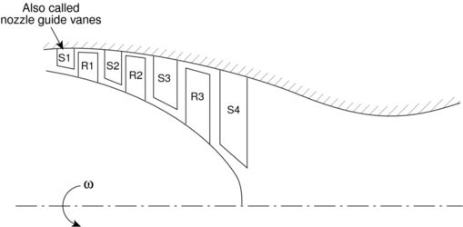
Next: 13. Aircraft Performance Up: 12. Energy Exchange with Previous: 12.5 Velocity Triangles for Contents Index 12.6 Velocity Triangles for an Axial Flow Turbine StageWe can apply the same analysis techniques to a turbine, Figure 12.8. The stator, again does no work. It adds swirl to the flow, converting internal energy into kinetic energy. The turbine rotor then extracts work from the flow by removing the kinetic energy associated with the swirl velocity. The appropriate velocity triangles are shown in Figure 12.9, where again the axial velocity was assumed to be constant for purposes of illustration. As we did for the compressor, we can write the Euler Turbine Equation in terms of useful design variables:
Next: 13. Aircraft Performance Up: 12. Energy Exchange with Previous: 12.5 Velocity Triangles for Contents Index |
![$\displaystyle 1-\frac{T_{Tc}}{T_{Tb}} = \frac{(\omega r)^2}{c_p T_{Tb}}\left[\f...
...\omega r}\tan\beta_b + \left(\frac{w_c}{\omega r} \tan\beta_c'-1\right)\right].$](img1580.png)