Subsections
14.3 Rocket Nozzles: Connection of Flow to Geometry
We have considered the overall performance of a rocket and seen that
is directly dependent on the exit velocity of the propellant.
Further, we have used the steady flow energy equation to determine
the exhaust velocity using the combustion chamber conditions and the
nozzle exit pressure. In this brief section, we will apply concepts
from thermodynamics and fluids to relate geometrical (design)
parameters for a rocket nozzle to the exhaust velocity.
We will make the following assumptions:
- The propellant gas obeys
the ideal gas law;
- The specific heat is constant;
- The flow in
the nozzle is one-dimensional;
- There are no losses due to friction;
- There is no heat transfer;
- The flow velocity in the combustion
chamber is negligible (zero); and
- The flow is steady.
Here we will use the ideal gas law,
and this expression for
an isentropic flow,
where  will be used to refer to a chamber upstream of the duct.
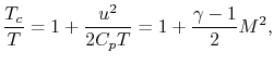
The first law for steady flow from
can be written in terms of
Mach number as
will be used to refer to a chamber upstream of the duct.
The first law for steady flow from
can be written in terms of
Mach number as
where it has been assumed that the velocity at
is small. From
these latter two equations it follows that
Conservation of mass states
All of these expressions can be combined to produce
The above equation relates the flow area, the mass flow, the Mach
number and the stagnation conditions (conditions at
). It is
frequently rewritten in a non-dimensional form by dividing through
by the value at  (where the area at
is
(where the area at
is  ):
):
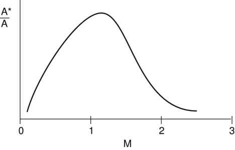
This equation takes a form something like that shown in Figure 14.4.
Figure 14.4:
General form of relationship between flow area and Mach
number.
|
|
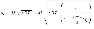
We can use these equations to rewrite our expression for rocket
thrust in terms of nozzle geometry (
 ),
and exit area,
),
and exit area,  . From before,
where
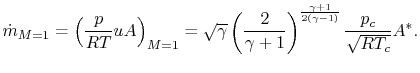
Evaluating the mass flow at the throat, where
,
The other terms in the thrust equation can be written in terms of
chamber and exit conditions:
and
We can now specify geometry (
and
) to determine  ,
and then use
with the combustion chamber conditions to
determine thrust and Isp.
UnifiedTP
,
and then use
with the combustion chamber conditions to
determine thrust and Isp.
UnifiedTP
|
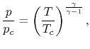
![$\displaystyle \frac{p_c}{p} = \left[1 + \frac{\gamma-1}{2}M^2\right]^{\frac{\gamma}{\gamma-1}}.$](img1698.png)
![$\displaystyle \dot{m} = \frac{P_c \sqrt{\gamma}}{\sqrt{R T_c}} \cfrac{M}{\left[1 + \cfrac{\gamma-1}{2}M^2\right]^{\frac{\gamma+1}{2(\gamma-1)}}}A.$](img1702.png)
![$\displaystyle \frac{A^*}{A}=\frac{1}{M}\left[\frac{2}{\gamma+1}\left(1 + \frac{\gamma-1}{2}M^2\right)\right]^{\frac{\gamma+1}{2(\gamma-1)}}.$](img1705.png)
![$\displaystyle \frac{P_e}{P_c} = \cfrac{1}{\left[1+\cfrac{\gamma-1}{2}M_e^2\right]^{\frac{\gamma}{\gamma-1}}}.$](img1711.png)