Subsections
6.4 Brayton Cycle in  -
- Coordinates
The Brayton cycle has two reversible adiabatic (i.e., isentropic)
legs and two reversible, constant pressure heat exchange legs. The
former are vertical, but we need to define the shape of the latter.
For an ideal gas, changes in specific enthalpy are related to
changes in temperature by
 , so the shape of the cycle
in an
, so the shape of the cycle
in an  -
plane is the same as in a
-
plane, with a scale
factor of
-
plane is the same as in a
-
plane, with a scale
factor of  between the two. This suggests that a place to start
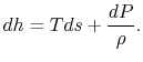
is with the combined first and second law, which relates changes in
enthalpy, entropy, and pressure:
between the two. This suggests that a place to start
is with the combined first and second law, which relates changes in
enthalpy, entropy, and pressure:
On constant pressure curves  and
and  . The quantity
desired is the derivative of temperature,
, with respect to
entropy,
, at constant pressure:
. The quantity
desired is the derivative of temperature,
, with respect to
entropy,
, at constant pressure:
 .
From the combined first and second law, and the relation between
.
From the combined first and second law, and the relation between
 and
and  , this is
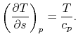 |
(6..2) |
The derivative is the slope of the constant pressure legs of the
Brayton cycle on a
-
plane. For a given ideal gas (specific
) the slope is positive and increases as
.
We can also plot the Brayton cycle in an
-
plane. This has
advantages because changes in enthalpy directly show the work of the
compressor and turbine and the heat added and rejected. The slope of
the constant pressure legs in the
-
plane is
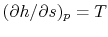 .
.
Note that the similarity in the shapes of the cycles in
-
and
-
planes is true for ideal gases only. As we will see when we
examine two-phase cycles, the shapes look quite different in these
two planes when the medium is not an ideal gas.
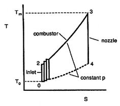
Figure 6.4:
Ideal Brayton cycle as
composed of many elementary Carnot cycles [Kerrebrock]
|
|
Plotting the cycle in
-
coordinates also allows another way to
address the evaluation of the Brayton cycle efficiency which gives
insight into the relations between Carnot cycle efficiency and
efficiency of other cycles. As shown in
Figure 6.4, we can break up the Brayton
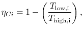
cycle into many small Carnot cycles. The ``
 '' Carnot
cycle has an efficiency of
'' Carnot
cycle has an efficiency of
where
the indicated lower temperature is the heat rejection temperature
for that elementary cycle and the higher temperature is the heat
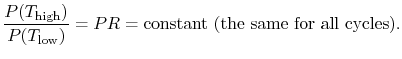
absorption temperature for that cycle. The upper and lower curves of
the Brayton cycle, however, have constant pressure. All of the
elementary Carnot cycles therefore have the same pressure ratio:
From the isentropic relations for an
ideal gas, we know that pressure ratio,  , and temperature ratio,
 , are related by:
 .
.
The temperature ratios
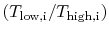 of any
elementary cycle ``i'' are therefore the same and each of the
elementary cycles has the same thermal efficiency. We only need to
find the temperature ratio across any one of the cycles to find what
the efficiency is. We know that the temperature ratio of the first
elementary cycle is the ratio of compressor exit temperature to
engine entry (atmospheric for an aircraft engine) temperature,
of any
elementary cycle ``i'' are therefore the same and each of the
elementary cycles has the same thermal efficiency. We only need to
find the temperature ratio across any one of the cycles to find what
the efficiency is. We know that the temperature ratio of the first
elementary cycle is the ratio of compressor exit temperature to
engine entry (atmospheric for an aircraft engine) temperature,
 in Figure 6.4. If the
efficiency of all the elementary cycles has this value, the
efficiency of the overall Brayton cycle (which is composed of the
elementary cycles) must also have this value. Thus, as previously,
in Figure 6.4. If the
efficiency of all the elementary cycles has this value, the
efficiency of the overall Brayton cycle (which is composed of the
elementary cycles) must also have this value. Thus, as previously,
Figure 6.5:
Arbitrary cycle operating
between
 ,
,

|
|
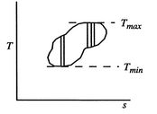
A benefit of this view of efficiency is that it allows us a way to
comment on the efficiency of any thermodynamic cycle. Consider the
cycle shown in Figure 6.5, which
operates between some maximum and minimum temperatures. We can break
it up into small Carnot cycles and evaluate the efficiency of each.
It can be seen that the efficiency of any of the small cycles drawn
will be less than the efficiency of a Carnot cycle between
and
. This graphical argument shows
that the efficiency of any other thermodynamic cycle operating
between these maximum and minimum temperatures has an efficiency
less than that of a Carnot cycle.
Muddy Points
If there is an ideal efficiency for all cycles, is there a maximum
work or maximum power for all cycles?
(MP 6.7)
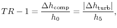
6.4.1 Net work per unit mass flow in a Brayton cycle
In Section 3.7.1 we found the net work of
a Brayton cycle in terms of heat transfer. Now that we have defined
entropy, we can reexamine the net work using an enthalpy-entropy
(
-
) diagram, Figure 6.6. The net mechanical
work of the cycle is given by:
where,
by the first law,
If kinetic energy changes across the compressor and turbine are
neglected, the temperature ratio,
, across the compressor and
turbine is related to the enthalpy changes:
The net work is thus
The turbine work is greater than the work needed to drive the
compressor, as is evident on the (
-
) diagram.
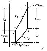
Figure 6.6:
Brayton cycle in enthalpy-entropy
(
-
) representation showing compressor and turbine work
|
|
Douglas Quattrochi
2006-08-06
|