


2.00b Toy Product Design
Let's Play - Toobers!
Electronics 4The First Circuit
The Breadboard
To prototype our circuit, we'll be using this nifty block of rectangle called a breadboard. A breadboard allows us to stick contacts directly into it, and have it electrically connected.
The horizontal rows (i.e. A1, B1, C1, D1 and E1) are all connected underneath. Note there is a middle channel that separates the two horizontal rows (sometimes called the trough) which separates the two sides (i.e. A1, B1, C1, D1 and E1 are NOT connected to F1, G1, H1, I1 and J1). On both ends are your power rails. Typically, the red one is connected to your power source (in this case 5v) and the black one is connected to your ground (in this case 0v). There are two power rails on both sides of the breadboard, which are NOT connected to one another (you'll see us use a jumper to bridge them later.)
In the image below, areas inside a purple outline are examples where points are connected together.

Wire Stripping
There are many sizes of wire for various applications. Larger diameter wires can handle more current. For breadboards, 22 AWG (American Wire Gauge) solid wire is commonly used (which is what you have in your kits!) The larger the number of the gauge, for example 26 AWG, the smaller the diameter of the conductor.
Most wires have a conductor in an insulating sheath. The ends of the wire are exposed by stripping the insulation off. Wire strippers have holes that are sized for the various gauges of wire. Place the wire in the hole that corresponds to the gauge of the wire.

If the hole is too small, the conductor will be nicked. If the hole is too big, the insulation will not be fully cut and may be difficult to remove. Once the wire is in the hole, squeeze the handles tightly to cut the insulation, then pull the wire stripper away at a slight angle (see video below).
When wiring breadboards, it's a good idea to plan where the wire starts and ends before cutting and stripping the wire. Properly sized wires result in neater breadboards, and neater breadboards are usually easier to debug. One process for stripping wires is as follows:
- Strip one end of the wire, about a quarter inch.
- Bend the stripped end and place it in the start hole.
- Measure the wire to the end hole.
- Add about a quarter inch and cut the wire.
- Strip the newly cut end of the wire.
- Bend the newly stripped end and place the wire in the start and end holes.
If the start and end holes are difficult to reach, a different set of holes the same distance apart may be used as a reference instead. If needed, watch the video below for a demonstration of the steps above.
Prepare the Bus Lines
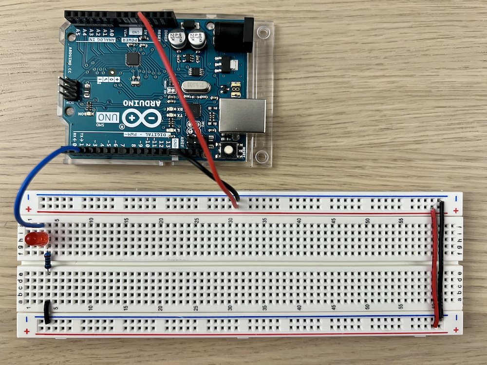
Our first step is to set up the power bus lines. Staying with convention, we will use the red buses for the 5V supply and the blue buses for ground (0V). For this part, we recommend that you strip your own hookup wire to keep things nice and neat. While not required, it's good practice to use red wire for the positive power supply and black wire for the ground, if those colors are available. We will not only connect the microcontroller's GND and 5V pins to the busses, but we will also connect the busses on the two sides of the breadboard so that the busses on both sides of the board can be used.
Wire the following:
- left-side blue bus to right-side blue bus
- left-side red bus to right-side red bus
While we may not be using both sides of these power rails just yet for this exercise, it's always a good idea to have them wired up. It'll save some headache later if you do decide to use them, (and wonder why it's not working if you don't wire them up)
Let's now bring in power to our breadboard by connecting the arduino's power (5v) and ground to the breadboard
- Connect Arduino 5V to a point on the red power rail
- Connect Arduino GND (you'll see multiple and they all do the same) to a point on the blue ground rail


The First Circuit
For our first circuit, we want to test the basic 'components' that are critical to the success of our toy. Doing a test like this is also called a sketch model (you'll learn more about this throughout the semester). For this first exercise, we're going to see if we can have the Arduino read one input (through the press of a button) and then output it (by turning an LED on for a set amount of time). Once we're reasonably comfortable with doing this, we'll be more confident when expanding it to 4 buttons and 4 lights, and eventually constructing our Toobers toy.
The circuit diagram we'll be following is shown below.

Let's start by assembling one LED. We've provided locations of pins as suggestions - as long as you have the right connections, you're good to go.
Note that there are two different resistors provided you in your kit! One is 220Ω, and the other is 1kΩ. You have 10 x 220Ω and 4 x 1kΩ. Please make sure that for the LEDs, you use the 220Ω resistors.
Protip: While you can use the color codes as a resistor to figure out the resistance, the quicker (and more 21st century method) is to use the multimeter you're given. Just turn it to the 'Ω' setting!
Take a look at the red LED in your kit. LEDs are light emitting diodes, and, as diodes, they have a polarity (they only allow current to flow in one direction.) LEDs indicate the polarity by having one terminal longer than the other.

- Bring Pin 2 of the Arduino PIN 2 to the board J3
- Grab the red LED. Place the longer end + into H3 and the shorter end - into H4.
- Place a resistor on the board (220Ω) from G4 to E4
- Finally, connect the resistor to ground A4 to Gnd
Note that you'll likely have red wire, black wire, and a random color in your kit. In general, you want to keep red and black consistent. The random color is there to help you distinguish the different wires (and so the actual wire color itself doesn't matter.)
Hooray! We have an LED connected to the board. We've placed a resistor in there to limit the amount of current going through the LED, to ensure it doesn't blow. Remember - if you're working with an LED on your own, always remember to use a resistor with it (unless otherwise specified!)
You may notice that your LED might be a tad bit long (sticking out of the board more than the picture) compared to the image above. You're free to trim it, but when trimming it, we recommend you maintain the difference in lengths between the long and the short LEDs, such that you don't forget the polarity.
Next, let's attach the button. If you grab one of the buttons from your kit, you'll notice it also has two contacts, which, very conveniently, will sit nicely into the breadboard. These buttons do not have polarity, but for them to work, the two contacts should be on different rows, e.g. row 2 and 4 (otherwise they're connected to each other, and always 'on'.) There's a little cap which can go onto the button, to give it some color and a slightly larger push area.
- Bring Pin 6 of the Arduino PIN 6 into the board J2
- Place a wire to jump across the trough G2 to E2
- Place a button on the board from the input line C2 to the ground C4


That's all for wiring! If we've done it correctly, we should now be able to control the LED and monitor the input from the code. Let's jump into the Arduino software now.
Open the file up in your Arduino IDE, and upload the file to the Arduino. Be sure your IDE is correctly configured and you've selected the right settings. If you don't remember this, you can always jump back to part 3 to take a look.
Once the code has uploaded (the TX/RX light should stop blinking) the new software should be on your Arduino! Go ahead and test it out. When you press the button and release, the light should blink twice.
If this looks correct, hooray! Take a few minutes to take a look at the code to see if you understand it.
Also note that on the Arduino, there is a reset button you can click (near the usb port). Clicking it is the same as unplugging and plugging in the Arduino.