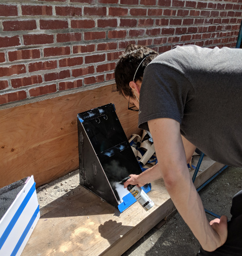
Blocks are first painted glossy black as a base texture...

The three main features of the game are the building blocks, the LED circuit, and the reset mechanism.
Building Blocks:
The building are the 3D puzzle pieces. Each building is comprised of a fixed foundation and 2 to 3 blocks of various shapes and sizes that stack on top of each other. However, the blocks are designed to slide and must be supported by propping a “bridge” block between adjacent buildings or by the players holding them in place with a hand, foot, knee, etc.
Blocks are first painted glossy black as a base texture...
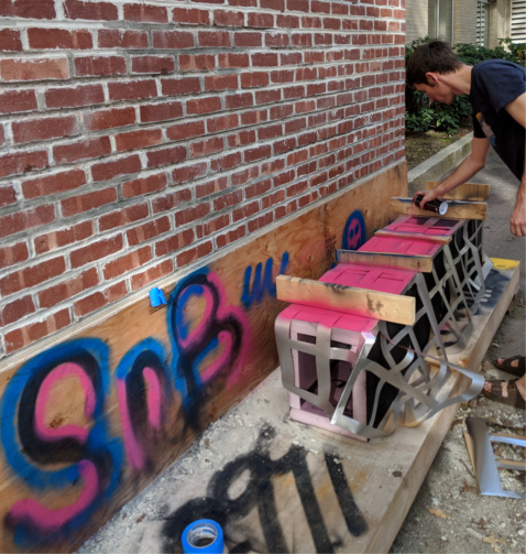
...followed by bright colors, determined by the building they belong to.
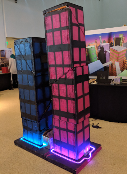
LED Lights:
At the base of each building is a ring of LEDs. Each building block contains a circuit and has electrical contacts at each surface. When the building is properly assembled, the circuit of that building will be completed and the LEDs will illuminate the building. This indicates to the players that they have solved one building correctly. Once every building in the room is illuminated, the players have won!
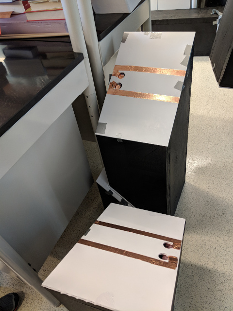
Copper contacts touch when a block is correctly placed...
...closing the circuit that signals the LED lights to turn on when a building is completed.
Reset Mechanism:
The room contains 10 buildings that, when complete, are supported by adjacent buildings through a bridge block or by the players. When the players exit the room, the pieces they were supporting will fall. In addition, 2 buildings will have hinged foundations that conceal linear actuators. These actuators will tip the foundations to about a 30 degree angle, causing a cascading effect in which all the building blocks and bridges fall apart.
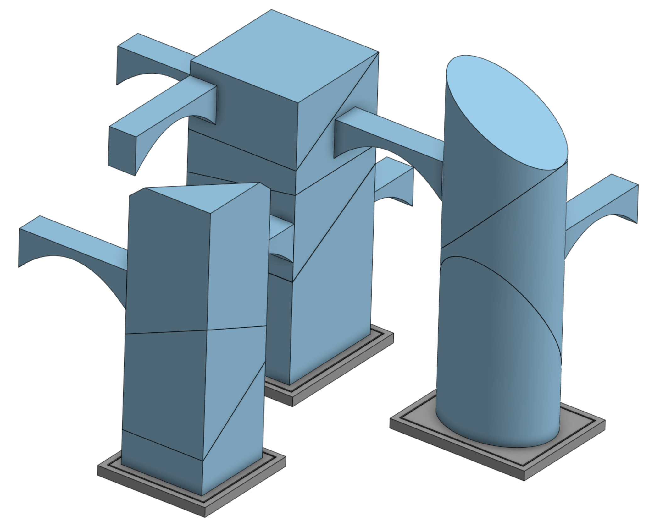
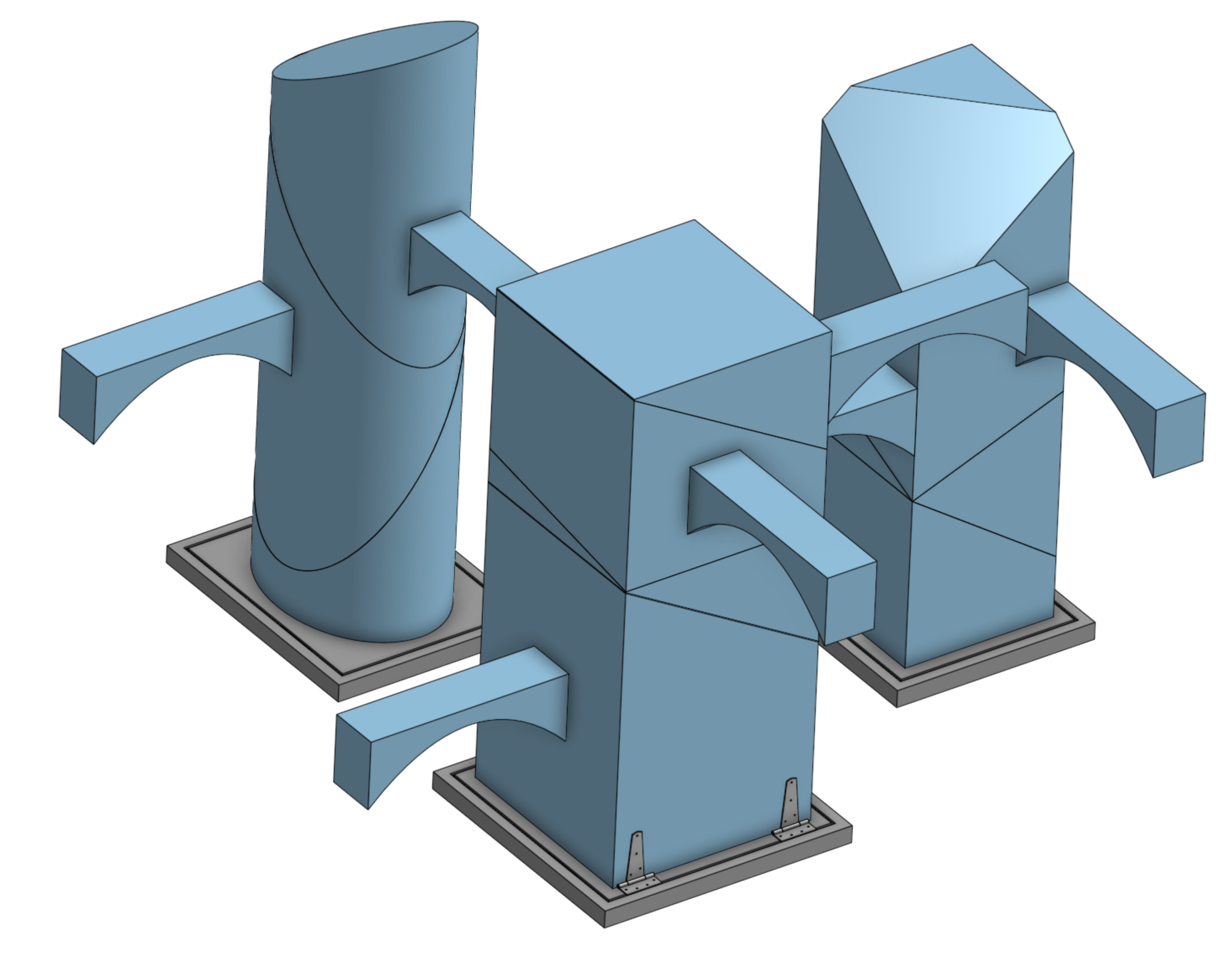
The 3D layout of the three-building cluster shows how each piece will support or be supported by its neighbors. The central building is internally supported with a pneumatic piston, while the surrounding buildings are only externally supported. The central building has three puzzle parts on top of its foundation, while the adjacent buildings have two.

When players correctly assemble a building, LEDs embedded in the base of the building will light up. As shown in the layout, this cluster will be repeated multiple times over to fill the room. The floor of the room will be covered in a grid of gym mats that are similar in size to the base of the buildings (shown in grey).
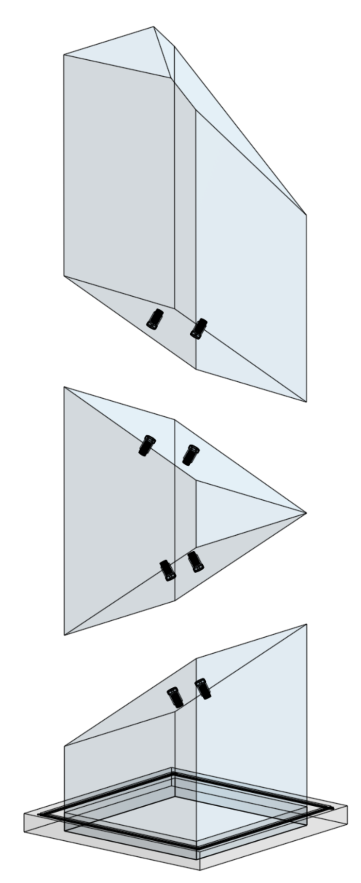
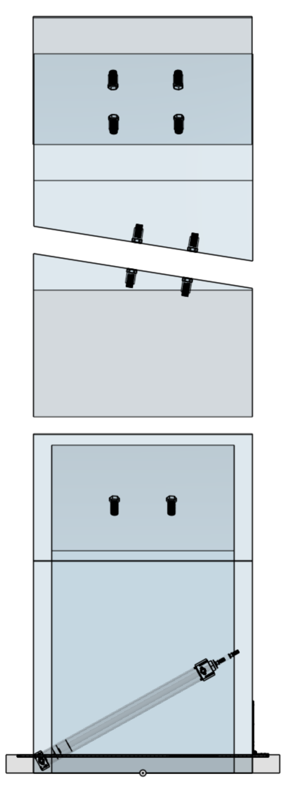
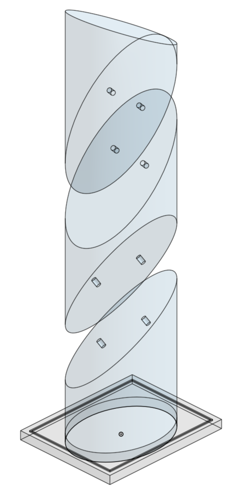
The translucent exploded view shows the internal details of each building. Each building block contains an internal circuit and contact pads on its top and bottom surfaces, which provide the electrical connection required to light up the LEDs when the building is correctly assembled. Further details on the circuit construction are shown below.
The center building also houses a pneumatic piston in its foundation that will tilt the base of this building to the side after the 3-minute time limit, causing the pieces above it to fall. As they fall, the pieces will no longer be able to support the bridges and adjacent building blocks, so all the buildings will tumble.
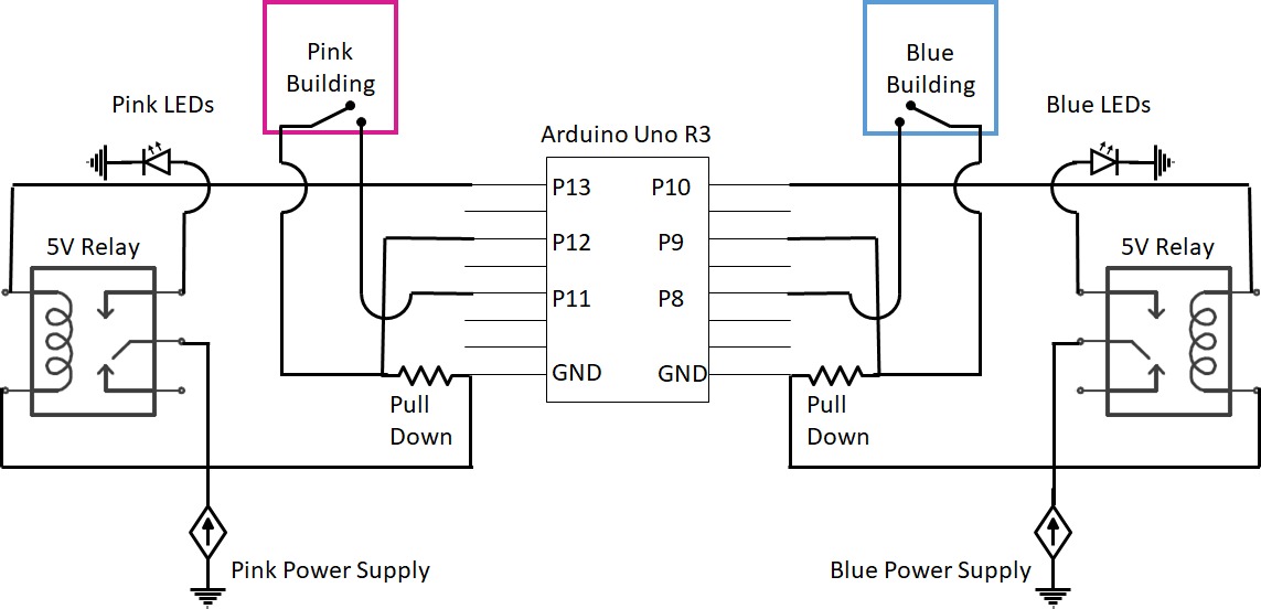
The basic principle of the circuit is that each building acts as a switch to turn on the LED at the base. This provides the user with feedback that the building was properly constructed. Instead of running electricity through the building, we used an Arduino R3 Uno to detect when each circuit was complete. The Arduino then output 5V to activate a relay switch which powered the appropriate set of LEDs.
The setup for each building is identical bar the pins used, blue pins are annotated in parenthesis. Two pins were used for each building. Pin 8 (11) was a constant output to the building while Pin 9 (5) was connected to the building and ground via a pull down resistor. When the building circuit was complete, Pin 9 (5) detected the complete circuit. When Pin 9 (5) detected the complete circuit, Pin 8 (11) ouputs 5V to the relay. This causes the relay to fire, connecting the LEDs to their power supply. We were able to control two sets of LEDs with one Arduino. An entire room would require a larger control board.
Pseudo-code for the setup:
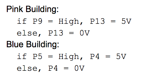
In an Arduino this code runs within a constantly repeating larger loop, meaning that the lights will automatically turn off if the building falls after completion. Issues with building block connections caused us to slightly modify this code. We turned on the lights once the building was complete and did not turn them off until the demo was complete. We discuss why this happened and possible remedies below.
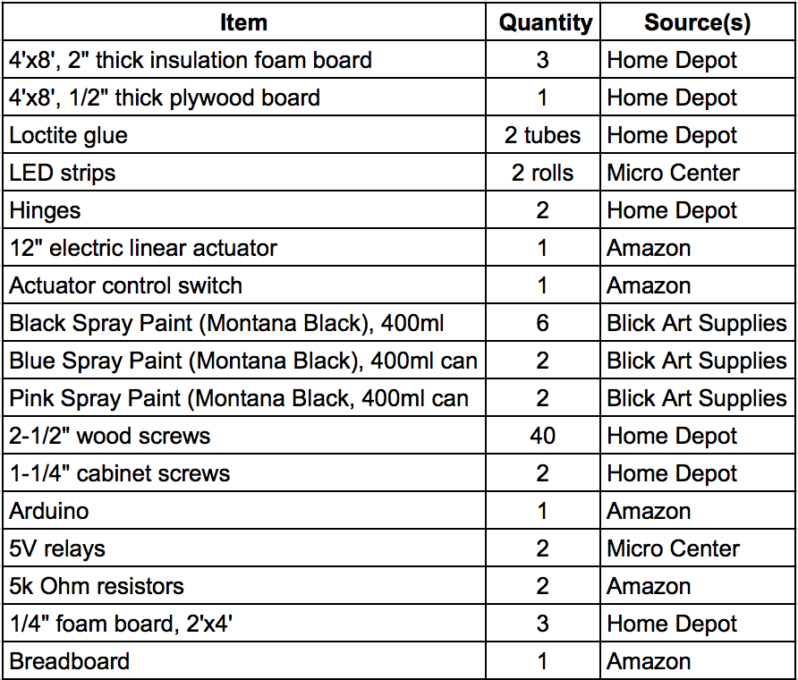
Below is the bill of materials for the buildings we actually built, but were we to have more time and money to develop this design for use, there are a number of things we would have done differently.
Circuit Robustness:
The main challenges in building our prototype was making a robust, building-sized circuit. We found that the copper tape was effective, but too thin on its own to reliably connect the circuit between building blocks. This meant our building circuit had a huge resistance, on the order of 10M Ohms. As a result, the microcontroller could barely detect the difference between an open circuit (incomplete building) and closed circuit (complete building). This meant the signal from the microcontroller was switching back and forth too quickly for the mechanical relay to react, creating unreliable LED feedback for the user.
One way to reduce this resistance would be to improve the contact reliability between building blocks by adding a thin layer of compliant foam between the copper tape and the building surfaces. This way, the contacts would be slightly raised off the surface and more likely to make a good connection when the building was assembled. In addition, a smaller pull-up resistor, either physically or in Arduino software, of 1-5k Ohms could be implemented in the circuit to ensure the microcontroller can clearly detect the difference between a closed and open building circuit. Finally, we were using a breadboard for our prototype, but the circuit robustness could be vastly improved by using soldered connections or a PCB.
Block Material Durability:
Another issue we faced was the durability of the blocks. We chose foam because we wanted the blocks to be light for safety reasons. However, the insulation foam we used in our prototype is not durable enough for continued use, as it cracks and indents very easily when it is dropped on blunt objects. In future iterations we would explore using EVA foam blocks or sheets to create the building blocks. Another option would be to laser cut and assemble acrylic molds for each block, and form whole blocks out of urethane foam. We would also recommend coating the outside of the finished blocks with some kind of clear varnish to preserve the external detailing.
Sliding Angle and Surface Finish:
The final issue we encountered was with the sliding interaction between the blocks. Based on our prototype, we suggest a sliding angle of 40 degrees or higher to ensure that the blocks reset properly. A thin acrylic sheet or varnish could also be applied at each interface, with cutouts for the electrical contact pads, to ensure uniform sliding.