Pressurized Tank

The two solenoid designs have their issues. The pin design has many components and its circuit board will be undoubtedly complicated. The gravity design has hefty strain concentrations in the lip edges. This design uses changes in pressure to drive gumdrop motion and locking. It attempts to simplify geometry and remove the stress pockets. Let's take a more in-depth look at the parts of this concept drawing.
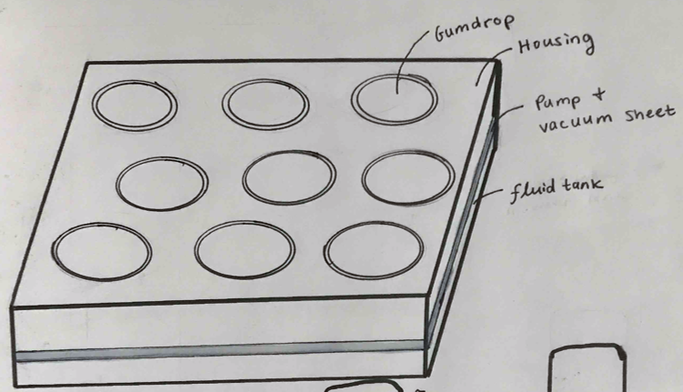
Here's a high level overview of the design. Again we have our housing with a lipped shaft grid and lipped gumdrops. Each shaft now has a valve and the housing + gumdrop assembly sits atop a pressurized tank. The tank could be filled with air, or water, or whatever fluid suits the application best.
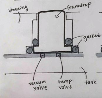
In its hidden state, the gumdrop sits in its shaft. It is not locked in place.

The pump valve opens and fluid from the tank rushes into the shaft. The bottom gasket keeps the fluid from leaking into other shafts. As fluid enters, it pushes the gumdrop up causing it to steadily rise.
Once the shaft is filled with fluid, the pump valve closes. The top gasket keeps the fluid from leaking out onto the housing. The fluid pressure inside the shaft bears the load of the structure and jumping people.

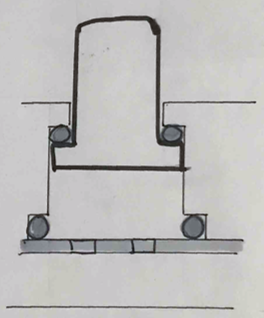
To lower the shaft the vacuum valve opens and fluid drains back into the tank. This negative pressure pulls the gumdrop back into the shaft until its base is flush with the floor.
Like the first design, no power is needed to maintain the gumdrop in its hidden and popped state. Power is only used in pumping and draining fluid to transition between the two states!
<< Check out the previous mechanism