Zipline: Works Like
Pseudogravity Failure Storyboard
Overview
I decided to make a works-like model for the Pseudogravity Failure Storyboard. The idea was to provide users with a fun, yet physically challenging way to get across the room without touching the ground. Below the design concepts, testing and lessons learned are described.
Mechanics
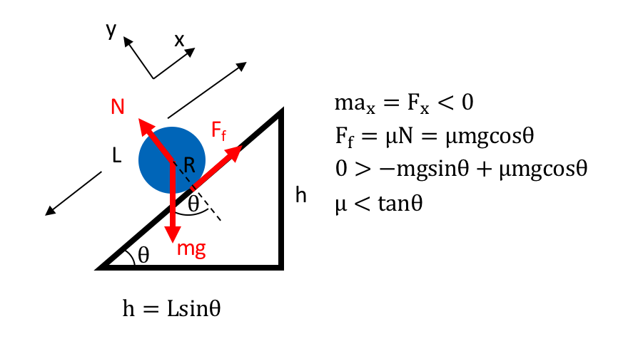
To model the physics of the design I created a simplified model of the zip line as a wheel rolling up an incline. I looked at the force balance equations to see what constraints were on the angles of incline for it to be able to overcome friction and roll back to the start. The calculations are shown below and show that we need the tangent of the incline angle to be greater than than the coefficient of static friction of the material for the zip line to be gravity resetting
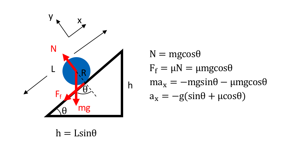
For rolling up the incline the calculations below show that we will have a negative acceleration up the incline, which will allow the zip line to be self-braking.
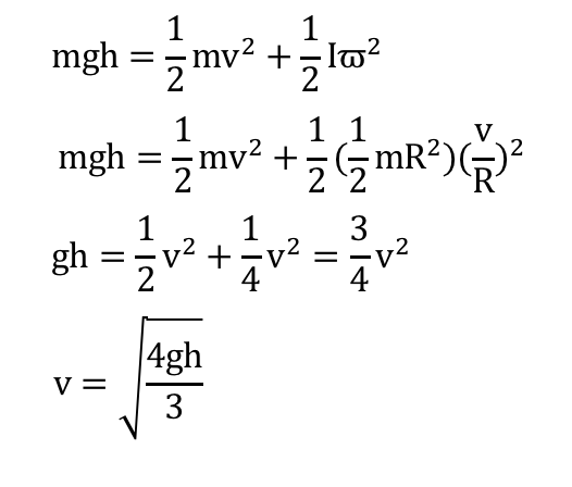
Also, an energy calculation was done to find the minimum initial velocity needed to get to the end of the zip line with zero velocity.
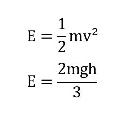
Finally, an energy calculation was done to find the energy of a push needed to get to the initial velocity required from above.
These calculations can be used to design a reasonable zip line that could be self-resetting and not require too much energy to use.
It should be noted that in all of these calculations it was assumed that there was static friction since the wheels are rolling, not sliding. It was also assumed that the frictional losses due to the wheel rods were minimal and could be reduced further with bearings. Also, the losses due to air drag were assumed to be minimal.
Design Concepts
The main design concept was to have the zip-line at an upwards slope, instead of the traditional downwards slope. This makes it physically challenging while allowing for it to be self-braking and self-resetting. The users are required to push off to make it to the other side and may have to do it multiple times if they don’t push hard enough the first time. Looking at the Mechanics section it can be seen that the mechanism is designed to use gravity to be self-resetting as well as self-braking (the user will have a negative acceleration).
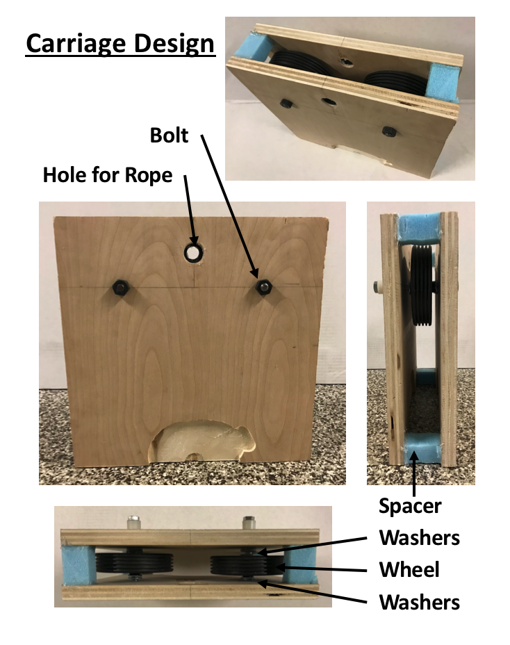
The carriage itself had a simple design for the sketch model. Training wheels were bolted together through two pieces of plywood. Spacers were added (blue foam) so that the sides of the carriage would not rub against the track. Also, washers were added at the sides of the wheels so that they would be centered within the carriage and on the track. Holes were drilled through the top of the carriage for the rope. Gaskets were also placed in these holes to minimize the abrasion of the rope. The rope was placed through the carriage and tied to a metal bar with handles, to allow users to hold on easier. The carriage fit easily on the 2X4 and 2X8 beam track.
Testing
We wanted to test the zip line to see if the self-resetting would work and to see how challenging it would be to use. We tested the gravity resetting by placing the beam on different rungs of the ladder and letting the carriage go from the top of the incline (see videos below). The first rung of the ladder was not enough of an incline to allow for self-resetting, but the second and third were.
We set the zip line back to the second rung and also tested pushing weighted backpacks and finally we tested the zip line ourselves (see videos below).
Learnings and Moving Forward
We had many different learnings from testing that we can implement in the next design iteration. First, we realized that it was easier for the user to face backwards and push off with their legs to make it up the incline. Therefore, the zip line design should have features to allow people to safely push off and land backwards. This could include extended landing pads and handles to grab onto, as well as an area to push off of and/or run off of. Also, we noticed that with the current set up, it was hard for taller people to use. Therefore, we should make the zip line taller and have ladders on each end so that people of different heights can use it. Also, the zip line should have a metal track to make more durable and bearings in the wheels to lessen frictional losses. Also, we will have to ensure that the rope, trolley, wheels and bearings are all rated to hold the required weight of a typical user. This was not implemented for the sketch model as it would have been too expensive for a first prototype. The next prototype will need more testing with various users and a longer track to see is different people of different heights can do it and what handle configuration they would prefer (i.e. using just a rope or a rod with handles or a seat).