
Laser Maze Tower Positioning System
This “works like” model explores some of the key physical features of the towers on which the mirrors are mounted in the laser maze. The height of the model is around 20in which is about one third of the expected height of the towers in the game. The following features of the towers were explored:
- How to restrict movement of the towers to one direction.
- How to lock the tower into a series of set positions to allow the lasers and sensors to work properly.
- Where should handles on the tower be placed for the users to slide them around.
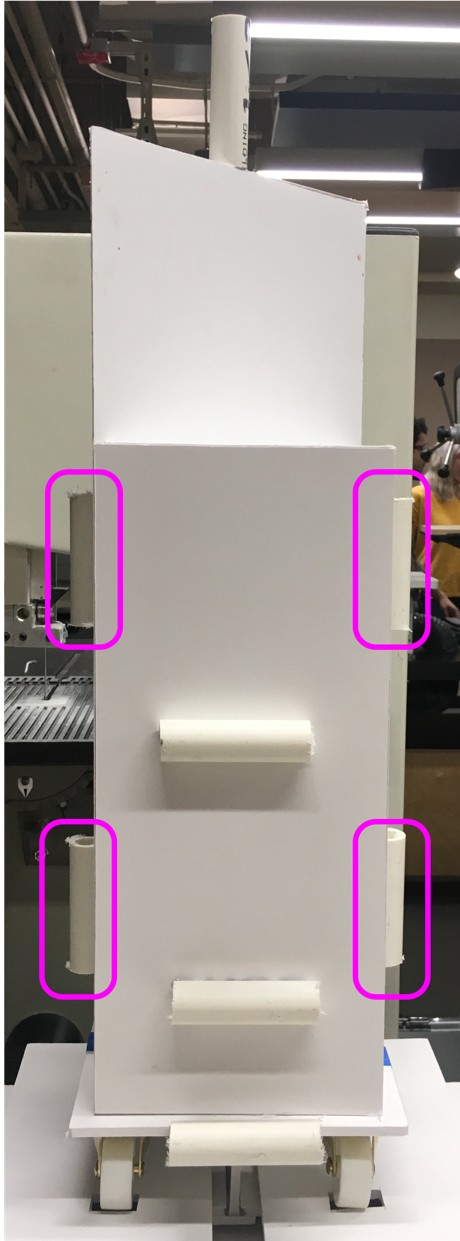
Restricting to 1D Movement
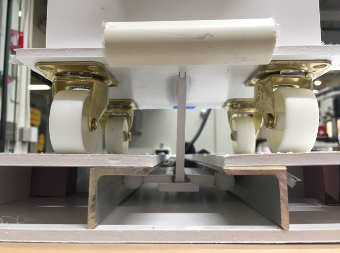
The platform for the tower is set on four caster wheels which have been glued so they stay in line with one direction on the grid. This however still allows for slipping from side to side. Through the center of the platform a fin extrudes below the floor fitting into a set of rails. This system works quite well allowing for smooth sliding of the towers in one direction and fixes each tower to one railing with the added benefit of not being able to be removed from the room. However, this below ground railing system will add complexity to the installation of the floor in the game room.
Locking Into Positions on the Grid
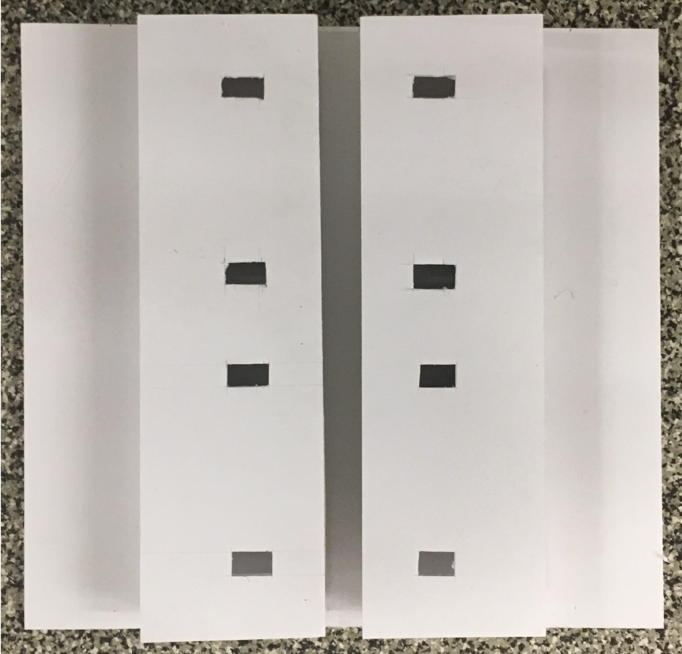
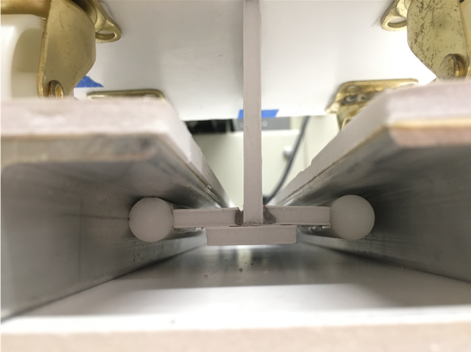
Because the lasers and sensors to detect them can be quite sensitive it is important that the towers lock into set positions to ensure the lasers to miss the sensors. To achieve this in the sketch model slots were inserted into the floor so the wheels below the platform would lock into place. The slots were made shallow enough so that the tower would lock into place but it is not too difficult to push the tower out of position and into another.
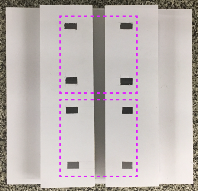
When testing this there was some confusion with an accidental intermediate position shown in the middle, lower image. This occurs because four slots were made to fit all four wheel but as you move from position one to position two, the back two wheels fall into the slots made for the front two wheels in position one. One alternative would be to either only have slots for one set of wheels(although that might cause tilts in the tower) , add a spring loaded pin that slides into slots on the floor or place the front and back wheels on different axis so they cant fall into the wrong slots.
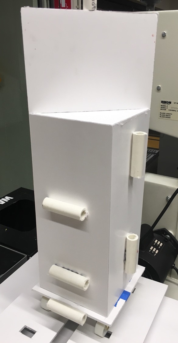
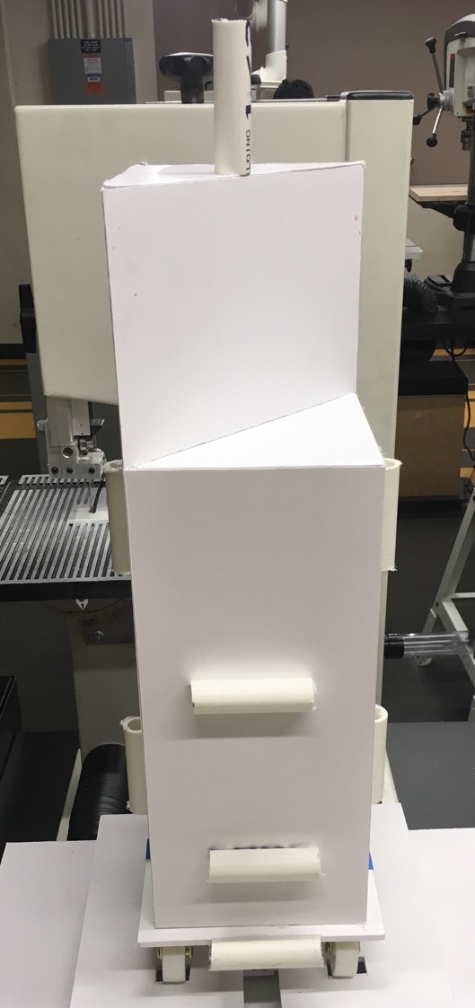
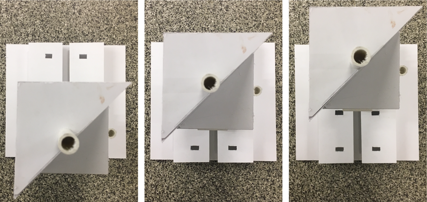
Handle Locations
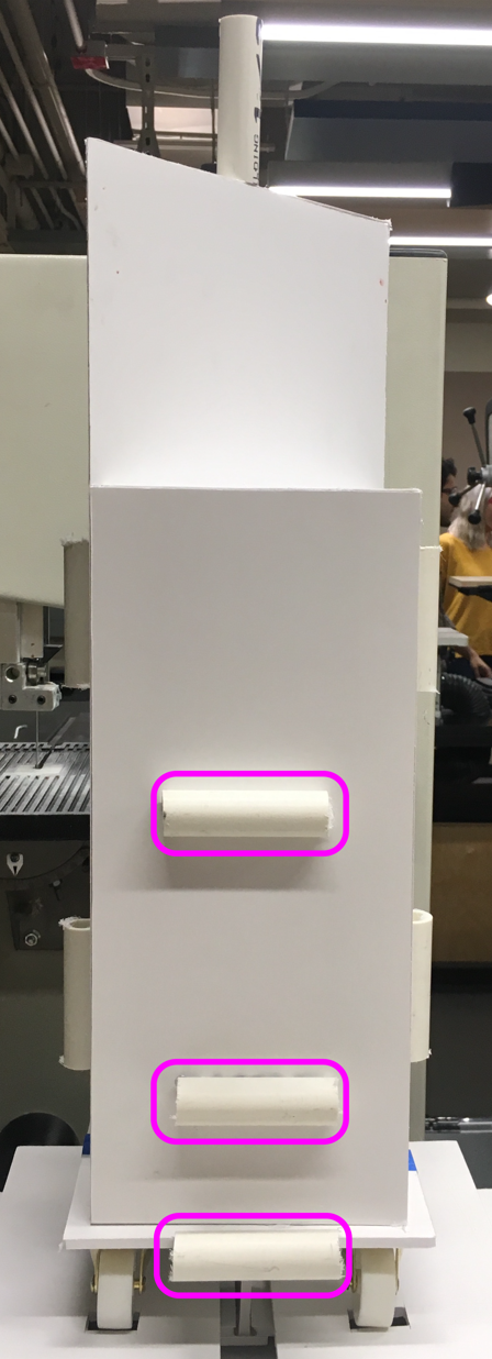
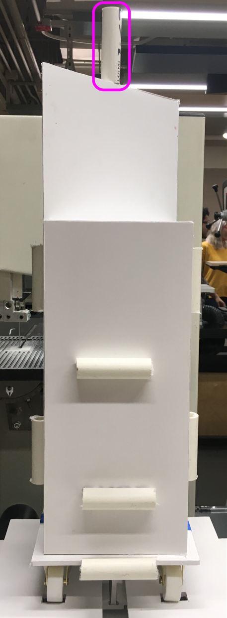
The location of the handle to push and pull the towers is affected by the user interaction as well as the physics and jamming of the wheels and bottom rail system. The top handle(right image) causes jamming and bending in the tower as does the higher handles in the left two images. It was found that the lower the handle, the smoother the sliding and from the “looks like” model a handle around hip height of the user along the axis of movement is the most effective and intuitive.