

| | Maxwell, Lorentz, and Newton
|
|---|
| 3.1.1 | In Example 3.1.1, it was shown that solutions to Maxwell's equations
can take the form E = Ex (z - ct)ix and H = Hy (z -
ct)iy in a region where J = 0 and  = 0. = 0.
| (a) | Given E and H by
(9) and (10) when t = 0, what are these fields for t > 0?
|
| (b) | By substituting these expressions into (1)-(4), show that
they are exact solutions to Maxwell's equations.
|
| (c) | Show that for an observer at z = ct + constant, these
fields are constant.
|
|
| 3.1.2* | Show that in a region where J = 0 and  = 0 and a solution to
Maxwell's equations E (r, t) and H (r, t) has been
obtained, a second solution is obtained by replacing H by
-E, E by H, = 0 and a solution to
Maxwell's equations E (r, t) and H (r, t) has been
obtained, a second solution is obtained by replacing H by
-E, E by H,  by by  and and  by by  . .
|
| 3.1.3 | In Prob. 3.1.1, the initial conditions given by (9) and (10) were
arranged so that for t > 0, the fields took the form of a wave
traveling in the +z direction.
| (a) | How would you alter the magnetic field
intensity, (10), so that the ensuing field took the form of a wave
traveling in the -z direction?
|
| (b) | What would you make H, so that
the result was a pair of electric field intensity waves having the
same shape, one traveling in the +z direction and the other traveling
in the -z direction?
|
|
| 3.1.4 | When t = 0, E = Eo iz cos  x, where Eo and x, where Eo and
 are given constants. When t = 0, what must H be to
result in E = Eo iz cos are given constants. When t = 0, what must H be to
result in E = Eo iz cos  (x - ct) for t > 0. (x - ct) for t > 0.
|
| | Quasistatic Laws |
|---|
| 3.2.1 | In Sec. 13.1, we will find that fields of the type considered in
Example 3.1.1 can exist between the plane parallel plates of Fig.
P3.2.1. In the particular case where the plates are "open" at the
right, where z = 0, it will be found that between the plates these
fields are

 where
where  = =    o o  o and Eo is a constant
established by the voltage source at the left. o and Eo is a constant
established by the voltage source at the left.
| (a) | By substitution,
show that in the free space region between the plates (where J = 0
and  =0), (a) and (b) are exact solutions to Maxwell's
equations. =0), (a) and (b) are exact solutions to Maxwell's
equations.
|
| (b) | Use trigonometric identities to show that these fields
can be decomposed into sums of waves traveling in the  z
directions. For example, Ex = E+ (z - ct) + E- (z + ct), where
c is defined by (3.1.16) and E z
directions. For example, Ex = E+ (z - ct) + E- (z + ct), where
c is defined by (3.1.16) and E are functions of z are functions of z  ct,
respectively. ct,
respectively.
|
| (c) | Show that if  l l  1, the time l/c
required for an electromagnetic wave to traverse the length of the
electrodes is short compared to the time 1, the time l/c
required for an electromagnetic wave to traverse the length of the
electrodes is short compared to the time   1/ 1/ within which the driving voltage is changing.
|
| (d) | Show that in the limit where this is true, (a) and (b)
become

 so that the electric field between the plates is uniform.
|
| (e) | With the frequency low enough so that (c) and (d) are good
approximations to
the fields, do these solutions satisfy the EQS or MQS laws? Is the
system EQS or MQS in this low-frequency limit?
|
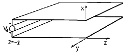 Figure P3.2.1
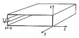 Figure P3.2.2
|
| 3.2.2 | In Sec. 13.1, it will be shown that the electric and magnetic
fields between the plane parallel plates of Fig. P3.2.2 are

 where
where  = =    o o  o and Ho is a constant
determined by the current source at the left. Note that because the
plates are "shorted" at z = 0, the electric field intensity given
by (a) is zero there. o and Ho is a constant
determined by the current source at the left. Note that because the
plates are "shorted" at z = 0, the electric field intensity given
by (a) is zero there.
| (a) | Show that (a) and (b) are exact solutions to
Maxwell's equations in the region between the plates
where J = 0 and  = 0. = 0.
|
| (b) | Use trigonometric identities to show that
these fields take the form of waves traveling in the  z directions
with the velocity c defined by (3.1.16). z directions
with the velocity c defined by (3.1.16).
|
| (c) | Show that the condition  l l  1 is equivalent to
the condition that the wave transit time l/c is short compared to 1 is equivalent to
the condition that the wave transit time l/c is short compared to
  1/ 1/ . .
|
| (d) | For the frequency  low enough so that the
conditions of (c) are satisfied,
give approximate expressions for E and H. Describe the
distribution of H between the plates. low enough so that the
conditions of (c) are satisfied,
give approximate expressions for E and H. Describe the
distribution of H between the plates.
|
| (e) | Are these approximate fields governed by the EQS or the MQS
laws?
|
|
| | Conditions for Fields to be Quasistatic |
|---|
| 3.3.1 | Rather than being in the circular geometry of Example 3.3.1, the
configuration considered here and shown in Fig. P3.3.1 consists of
plane parallel rectangular electrodes of (infinite) width w in the
y direction, spacing d in the x direction and length 2l in the
z direction. The region between these electrodes is free space.
Voltage sources constrain the integral of E between the electrode
edges to be the same functions of time.

| (a) | Assume that the voltage sources are varying so slowly that
the electric field is essentially static (irrotational). Determine the
electric field between the electrodes in terms of v and the
dimensions. What is the surface charge density on the inside surfaces
of the electrodes? (These steps are very similar to those in
Example 3.3.1.)
|
| (b) | Use conservation of charge to determine the surface
current density Kz on the electrodes.
|
| (c) | Now use Ampère's
integral law and symmetry arguments to find H. With this field
between the plates, use Ampère's continuity condition,
(1.4.16), to find K in the plates and show that it is consistent
with the result of part (b).
|
| (d) | Because of the H found in part
(c), E is not irrotational. Return to the integral form of
Faraday's law to find a corrected electric field intensity, using the
magnetic field of part (c). [Note that the electric field found in
part (a) already satisfies the conditions imposed by the voltage
sources.]
|
| (e) | If the driving voltage takes the form v = vo cos  t, determine the ratio of the correction (error) field to the
quasistatic field of part (a).
|
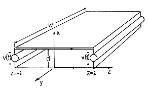 Figure P3.3.1
|
| 3.3.2 | The configuration shown in Fig. P3.3.2 is similar to that for
Prob. 3.3.1 except that the sources distributed along the left and
right edges are current rather than voltage sources and are of
opposite rather than the same polarity. Thus, with the current
sources varying slowly, a (z-independent) surface current density
K(t)
circulates around a loop consisting of the sources and the electrodes.
The roles of E and H are the reverse of what they were in
Example 3.3.1 or Prob. 3.3.1. Because the electrodes are pictured as
having no resistance, the low-frequency electric field is zero while,
even if the excitations are constant in time, there is an H. The
following steps answer the question, Under what circumstances is the
electric displacement current negligible compared to the magnetic
induction?
| (a) | Determine H in the region between the electrodes in a
manner consistent with there being no H outside. (Ampère's
continuity
condition relates H to K at the electrodes. Like the E
field in Example 3.3.1 or Prob. 3.3.1, the H is
extremely simple.)
|
| (b) | Use the integral form of Faraday's law to
determine E between the electrodes. Note that symmetry requires
that this field be zero where z = 0.
|
| (c) | Because of this time-varying
E, there is a displacement current density between the electrodes
in the x direction. Use Ampère's integral law to find the correction
(error) H. Note that the quasistatic field already meets the
conditions imposed by the current sources where z =  l. l.
|
| (d) | Given that the driving currents are sinusoidal with angular
frequency  , determine the ratio of the "error" of H to
the MQS field of part (a). , determine the ratio of the "error" of H to
the MQS field of part (a).
|
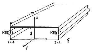 Figure P3.3.2
|
| | Quasistatic Systems |
|---|
| 3.4.1 | The configuration shown in cutaway view in Fig. P3.4.1 is
essentially the outer region of the system shown in Fig. 3.4.2. The
object here is to determine the error associated with neglecting the
displacement current density in this outer region. In this problem,
the region of interest is pictured as bounded on three sides by
material having no resistance, and on the fourth side by a distributed
current source. The latter imposes a surface current density Ko
in the z direction at the radius r = b. This current passes radially
outward through a plate in the z = h plane, axially downward in another
conductor at the radius r = a, and radially inward in the plate at z
= 0.
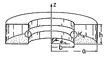 Figure P3.4.1
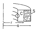 Figure P3.4.2
| (a) | Use the MQS form of Ampère's integral law to determine H inside the "donut"-shaped region. This field should be
expressed in terms of Ko. (Hint: This step is essentially the same
as for Example 3.4.1.)
|
| (b) | There is no H outside the structure. The
interior field is terminated on the boundaries by a surface current
density in accordance with Ampère's continuity condition. What is
K on each of the boundaries?
| | (c) | In general, the driving current is time varying, so Faraday's law requires that there be an electric
field. Use the integral form of this law and the contour C and
surface S shown in Fig. P3.4.2 to determine E. Assume that E
tangential to the zero-resistance boundaries is zero. Also, assume
that E is z directed and independent of z.
|
| (d) | Now determine the error in the
MQS H by using Ampère's integral law. This time the displacement
current density is not approximated as zero but rather as implied by
the E found in part (c). Note that the MQS H field already
satisfies the condition imposed by the current source at r = b.
|
| (e) | With Ko = Kp cos  t, write the condition for the
error field to be small compared to the MQS field in terms of t, write the condition for the
error field to be small compared to the MQS field in terms of  , c, and l.
|
|
|


 = 0.
= 0.
 = 0 and a solution to
Maxwell's equations E (r, t) and H (r, t) has been
obtained, a second solution is obtained by replacing H by
-E, E by H,
  by
by  and
and  by
by  .
.
 x, where Eo and
 are given constants. When t = 0, what must H be to
result in E = Eo iz cos
  (x - ct) for t > 0.


 =
= 

 o
o  o and Eo is a constant
established by the voltage source at the left.


 =
= 

 o
o  o and Ho is a constant
determined by the current source at the left. Note that because the
plates are "shorted" at z = 0, the electric field intensity given
by (a) is zero there.


 z
directions. For example, Ex = E+ (z - ct) + E- (z + ct), where
c is defined by (3.1.16) and E
 1, the time l/c
required for an electromagnetic wave to traverse the length of the
electrodes is short compared to the time
 1/
1/
