The potential distribution in a dielectric that is free of unpaired charge and which has a space-varying permittivity is governed by

This is (6.5.1) combined with (6.5.2) and with  u = 0. The
contribution of the spatially
varying permittivity is emphasized by using the vector identity for
the divergence of a scalar (
 ) times a vector (
 ).
).

With a spatially varying permittivity, polarization charge is induced
in proportion to the component of E that is in the direction of the
gradient in  . Thus, in general, the potential is not a
solution to Laplace's equation.
Equation (2) gives a different perspective to the approach taken in
dealing with piece-wise uniform systems. In Sec. 6.6, the
polarization charge density represented by the 
 term
in (2) is
confined to interfaces and accounted for by jump conditions. Thus,
the section was a variation on the theme of Laplace's equation. The theme
of this section broadens the developments of Sec. 6.6.
It is the objective in this section to demonstrate how familiar
methods are adapted to dealing with unfamiliar laws. In general,
(2) has spatially varying coefficients. Thus, even though it is linear,
we are not guaranteed simple closed-form solutions. However, if the
spatial dependence of  is exponential, the equation does have
constant coefficients and simple solutions. Our example exploits this
fact.
Example 6.7.1. Fields in an Exponentially Varying Dielectric
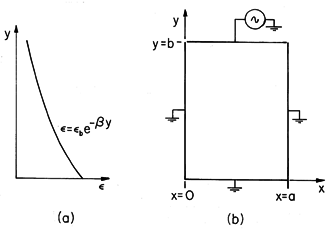
A dielectric has a permittivity that varies exponentially in the y direction, as illustrated in Fig. 6.7.1a.
Here
p and
are given constants.
Figure 6.7.1 (a) Smooth permittivity distribution of material enclosed by (b) zero potential boundaries at x = 0, x = a, and y = 0, and electrode at potential v at y = b. In this example, the dielectric fills the rectangular region shown in Fig. 6.7.1b. This configuration is familiar from Sec. 5.5. The fields are two dimensional,
= 0 at x = 0 and x = a and y = 0. The potential on the "last" surface, where y = b, is v(t).
It follows from (3) that
and (2) becomes
The dielectric fills a region having boundaries that are natural in Cartesian coordinates. Thus, we look for product solutions having the form
= X(x) Y(y). Substitution into (5) gives
The first term, a function of y alone, must sum with the function of x alone to give zero. Thus, the first is set equal to the separation coefficient k2 and the second equal to -k2.
This assignment of sign for the separation coefficient is motivated by the requirement that
= 0 at two locations. This results in periodic solutions for (7).
Because it also has constant coefficients, the solutions to (8) are exponentials. Substitution of exp (py) shows that
and it follows that solutions are linear combinations of two exponentials.
For the specific problem at hand, we look for the products of these sets of solutions that satisfy the homogeneous boundary conditions. Those at x = 0 and x = a are met by making k = n
/a, with n an integer. The origin of the y axis was made to coincide with the third zero potential boundary so that the hyperbolic sine function could be used. Thus, we arrive at an infinite series of solutions, each satisfying the homogeneous boundary conditions.
The assignment of the coefficients so that the potential constraint at y = b is met follows the procedure familiar from Sec. 5.5.
For interpretation of (13), suppose that
is positive so that
decreases with y, as illustrated in Fig. 6.7.1a. Without the analysis, we know that the lines of D originate on the electrode at y = b and terminate on the zero potential walls. This means that E lines either terminate on the grounded walls or on polarization charges induced in the volume. If v > 0, we can see from (6.5.9) that because E


is positive, the induced polarization charge density must be negative. Thus, some of the E lines terminate on this negative charge density and it comes as no surprise that we have found a potential that decays away from the excitation electrode at y = b at a rate that is faster than if the potential were governed by Laplace's equation. The electric field is effectively shielded out of the lower region of higher permittivity by the induced polarization charge.
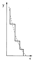
One approach to determining fields in spatially varying dielectrics is suggested in Fig. 6.7.2. The smooth distribution has been approximated by "stair steps." Physically, the equivalent system consists of uniform layers. Thus, the fields revert to the solutions of Laplace's equation matched to each other at the interfaces by the jump conditions. According to (6.5.11), E lines originating at y = b and passing downward through these interfaces will induce positive surface polarization charge. Thus, replacing the smoothly varying dielectric with the layers of uniform dielectric is equivalent to representing the volume polarization charge density by a distribution of surface polarization charges.


