In a region where the permittivity is uniform and where there is no unpaired charge, the electric potential obeys Laplace's equation.

This follows from (6.5.1) and (6.5.2).
Uniform Dielectrics
If all of the region of interest is filled by a
uniform dielectric, it is clear from the foregoing that all equations
developed for fields in free space are now valid in the presence of
the uniform dielectric. The only alteration is the replacement of
the permittivity of free space  o by that of the uniform
dielectric. In every problem from Chaps. 4 and 5 where
  and
E were determined in a region of free space bounded by
equipotentials, that region could just as well be filled with a
uniform dielectric, and for the same potentials the electric field
intensity would be unaltered. However, the surface charge density
 su on the boundaries would then be increased by the ratio
 /
/ o.
o.
Illustration. Capacitance of a Sphere
A sphere having radius R has a potential v relative to infinity. Formally, the potential, and hence the electric field, follow from (1).
Evaluation of the capacitance, (6.5.6), then gives
The dielectric has increased the capacitance in the ratio of the dielectric constant of the material to the dielectric constant of free space.
The susceptibilities listed in Table 6.4.1 illustrate the increase in capacitance that would be observed if vacuum were replaced by one of the materials. In gases, atoms or molecules are so dilute that the increase in capacitance is usually negligible. With solids and liquids, the increase is of practical importance. Some, having molecules of large permanent dipole moments that are aligned by the field, increase the capacitance dramatically.
The following example is intended to provide an appreciation for why the polarized dielectric increases the capacitance.
Example 6.6.1. An Artificial Dielectric
In the plane parallel capacitor of Fig. 6.6.1, the electric field intensity is (v/d)iz. Thus, the unpaired charge density on the lower electrode is Dz =
v/d, and if the electrode area is A, the capacitance is
Here we assume that d is much less than either of the electrode dimensions, so the fringing fields can be ignored.
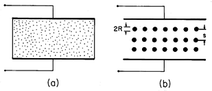
Figure 6.6.1 (a) Plane parallel capacitor with region between electrodes occupied by a dielectric. (b) Artificial dielectric composed of cubic array of perfectly conducting spheres having radius R and spacing s. Now consider the plane parallel capacitor of Fig. 6.6.1b. The dielectric is composed of "molecules" that are actually perfectly conducting spheres. These have radius R and are in a cubic array with spacing s >> R. With the application of a voltage, the spheres acquire the positive and negative surface charges on their northern and southern poles required to make their surfaces equipotentials. In so far as the field outside the spheres is concerned, the system is modeled as an array of dipoles, each induced by the applied field.
If there are many of the spheres, the change in capacitance caused by inserting the array between the plates can be determined by treating it as a continuum. This we will do under the assumption that s >> R. In that case, the field in regions removed several radii from the sphere centers is essentially uniform, and taken as Ez = v/d. The resulting field in the vicinity of a sphere is then as determined in Example 5.9.1. The dipole moment of each sphere follows from a comparison of the potential for the perfectly conducting sphere in a uniform electric field, (5.9.7), with that of a dipole, (4.4.10).
The polarization density is the moment/dipole multiplied by the number of dipoles per unit volume, the number density N.
For the cubic array, a unit volume contains 1/s3 spheres, and so
From (6) and (7) it follows that
Thus, the polarization density is a linear function of E. The susceptibility follows from a comparison of (8) with (6.4.2) and, in turn, the permittivity is given by (6.4.4).
Of course, this expression is accurate only if the interaction between spheres is negligible.
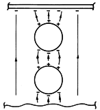
As the array of spheres is inserted between the electrodes, surface charges are induced, as shown in Fig. 6.6.2. Within the array, each cap of positive surface charge on the north pole of a sphere is compensated by an opposite charge on the south pole of a neighboring sphere. Thus, on a scale large compared to the spacing s, there is no charge density in the volume of the array. Nevertheless, the average field at the electrode is larger than the applied field Ea. This is caused by surface charges on the last layers of spheres which have their images in unpaired charges on the electrodes. For a given applied voltage, the field between the top and bottom layers of spheres and the adjacent electrodes is increased, with an attendant increase in observed capacitance.
Figure 6.6.2 From the microscopic point of view, the increase in capacitance results because the dipoles adjacent to the electrode induce image charges on the electrode in addition to those from the unpaired charges on the opposite electrode.
 Demonstration 6.6.1. An Artificial Dielectric
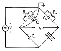
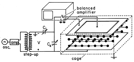
In Fig. 6.6.3, the artificial dielectric is composed of an array of ping-pong balls with conducting coatings. The parallel plate capacitor is in one leg of a bridge, as shown in the circuit pictured in Fig. 6.6.4. The resistors shunt the input terminals of balanced amplifiers so that the oscilloscope displays vo. With the array removed, capacitor C2 is adjusted to null the output voltage vo. The output voltage resulting from the the insertion of the array is a measure of the change in capacitance. To simplify the interpretation of this voltage, the resistances Rs are made small compared to the impedance of the parallel plate capacitor. Thus, almost all of the applied voltage V appears across the lower legs of the bridge. With the introduction of the array, the change in current through the parallel plate capacitor is
Figure 6.6.4 Balanced amplifiers of oscilloscope, balancing capacitors, and demonstration capacitor shown in Fig. 6.6.4 comprise the elements in the bridge circuit. The driving voltage comes from the transformer, while vo is the oscilloscope voltage.
Thus, there is a change of current through the resistance in the right leg and hence a change of voltage across that resistance given by
Because the current through the left leg has remained the same, this change in voltage is the measured output voltage.
Typical experimental values are R = 1.87 cm, s = 8 cm, A = (0.40)2 m2, d = 0.15 m,
= 2
(250 Hz), Rs = 100 k\Omega and V = 566 v peak with a measured voltage of vo = 0.15 V peak. From (4), (9), and (11), the output voltage is predicted to be 0.135 V peak.
Piece-Wise Uniform Dielectrics
So far we have only considered systems filled with uniform dielectrics, as in Fig. 6.5.1a. We turn now to the description of fields in piece-wise uniform dielectrics, as exemplified by Fig. 6.5.1b.
In each of the regions of constant permittivity, the field distribution is described by Laplace's equation, (1). The field problem is attacked by solving this equation in each of the regions and then using the jump conditions to match these solutions at the surfaces of discontinuity between the dielectrics. The following example has a relatively simple solution that helps form further insights.
Example 6.6.2. Dielectric Rod in Uniform Transverse Field
A uniform electric field Eo ix, perhaps produced by means of a parallel plate capacitor, exists in a dielectric having permittivity
a. With its axis perpendicular to this field, a circular cylindrical dielectric rod having permittivity
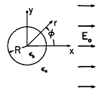
b and radius R is introduced, as shown in Fig. 6.6.5. With the understanding that the electrodes are sufficiently far from the rod so that the field at "infinity" is essentially uniform, our objective is to determine and then interpret the electric field inside and outside the rod.
Figure 6.6.5 Insulating rod having uniform permittivity b surrounded by material of uniform permittivity
a. Uniform electric field is imposed by electrodes that are at "infinity."
The shape of the circular cylindrical boundary suggests that we use polar coordinates. In these coordinates, x = r cos
, and so the potential far from the cylinder is
Because this potential varies like the cosine of the angle, it is reasonable to attempt satisfying the jump conditions with solutions of Laplace's equation having the same
dependence. Thus, outside the cylinder, the potential is assumed to take the form
Here the dipole field is multiplied by an adjustable coefficient A, but the uniform field has a magnitude set to match the potential at large r, (12).
Inside the cylinder, the solution with a 1/r dependence cannot be accepted because it becomes singular at the origin. Thus, the only solution having the cosine dependence on
is a uniform field, with the potential
Can the coefficients A and B be adjusted to satisfy the two jump conditions implied by the laws of Gauss and Faraday, (6.5.3) and (6.5.4), at r = R?
Substitution of (13) and (14) into these conditions shows that the answer is yes. Continuity of potential, (16), requires that
while continuity of normal D, (15), is satisfied if
Note that these conditions contain the cos
dependence on both sides, and so can be satisfied at each angle
. This confirms the correctness of the originally assumed
dependence of our solutions. Simultaneous solution of (17) and (18) for A and B gives
Introducing these values of the coefficients into the potentials, (13) and (14), gives
The electric field is obtained as the gradient of this potential.
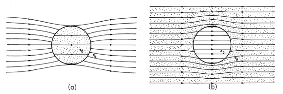
Figure 6.6.6 Electric field intensity in and around dielectric rod of Fig. 6.6.5 for (a) b >
a and (b)
b

a.
The electric field intensity given by these expressions is shown in Fig. 6.6.6. If the cylinder has the higher dielectric constant, as would be the case for a dielectric rod in air, the lines of electric field intensity tend to concentrate in the rod. In the opposite case- for example, representing a cylindrical void in a dielectric- the field lines tend to skirt the cylinder.
With an understanding of the relationship between the electric field intensity and the induced polarization charge comes the ability to see in advance how dielectrics distort the electric field. The circular cylindrical dielectric rod introduced into a uniform tranverse electric field in Example 6.6.2 serves as an illustration. Without carrying out the detailed analysis which led to (23) and (24), could we see in advance that the electric field has the distribution illustrated in Fig. 6.6.6?
The induced polarization charge provides the sources for the field induced by polarized material. For piece-wise uniform dielectrics, this is a polarization surface charge, given by (6.5.11).

The electric field intensity in the cylindrical rod example is
generally directed to the right. It
follows from (25) that the distribution of surface polarization
charge at the cylindrical interface is as illustrated in Fig. 6.6.7.
With the rod having the higher permittivity, Fig. 6.6.7a, the
induced positive polarization surface charge density is at the right and
the negative surface charge is at the left. These charges give rise to
fields that generally originate at the positive charge and terminate
at the negative. Thus, it is clear without any analysis that if  b
>
b
>  a,
the induced field inside tends to cancel the imposed field. In this
case, the interior field is decreased or "depolarized." In the
exterior region, vector addition of the induced field to the
right-directed imposed field shows that incoming field lines at the left
must be deflected inward, while outgoing ones at the right are deflected
outward.
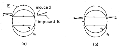
 b >
b >  a, (b)
  a >
a >  b.
b.
These same ideas, applied to the case where  a >
a >  b, show that
the interior field is increased while the exterior one tends to be ducted
around the cylinder.
The circular cylinder is one of a series of examples having exact solutions. These give the opportunity to highlight the physical phenomena without encumbering mathematics. If it is actually necessary to account for detailed geometry, then some of the approaches introduced in Chaps. 4 and 5 can be used. The following example illustrates the use of the orthogonal modes approach introduced in Sec. 5.5.
Example 6.6.3. Fringing Field of Dielectric Filled Parallel Plate Capacitor
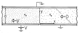
Fields are to be determined in the planar region between a grounded conductor in the plane y = a and a pair of conductors in the plane y = 0, shown in Fig. 6.6.8. To the right of x = 0 in the y = 0 plane is a second grounded conductor. To the left of x = 0 in this same plane is an electrode at the potential V. The regions to the right and left of the plane x = 0 are, respectively, filled with uniform dielectrics having permittivities
a and
b. Under the assumption that the system extends to infinity in the \pm x and \pm z directions, we now determine the fringing fields in the vicinity of the interface between dielectrics.
Figure 6.6.8 Grounded upper electrode and lower electrode extending from x = 0 to x 
form plane parallel capacitor with fringing field that extends into the region 0 < x between grounded electrodes.
Our approach is to write solutions to Laplace's equation in the respective regions that satisfy the boundary conditions in the planes y = 0 and y = a and as x
\pm
. These are then matched up by the jump conditions at the interface between dielectrics.
Consider first the region to the right, where
= 0 in the planes y = 0 and y = a and goes to zero as x

. From Table 5.4.1, we select the infinite set of solutions
Here we have set k = n
/a so that the sine functions are zero at each of the boundaries.
In the region to the left, the field is uniform in the limit x
-
. This suggests writing the solution as the sum of a "particular" part meeting the "inhomogeneous part" of the boundary condition and a homogeneous part that is zero on each of the boundaries.
The coefficients An and Bn must now be adjusted so that the jump conditions are met at the interface between the dielectrics, where x = 0. First, consider the jump condition on the potential, (6.5.4). Evaluated at x = 0, (26) and (27) must give the same potential regardless of y.
To satisfy this relation at each value of y, expand the linear potential distribution on the right in a series of the same form as the other two terms.
Multiplication of both sides by sin (m
y/a) and integration from y = 0 to y = a gives only one term on the right and an integral that can be carried out on the left. Hence, we can solve for the coefficients Vn in (29).
Thus, the series provided by (29) and (30) can be substituted into (28) to obtain an expression with each term a sum over the same type of series.
This expression is satisfied if the coefficients of the like terms are equal. Thus, we have
To make the normal component of D continuous at the interface,
and a second relation between the coefficients results.
The coefficients An and Bn are now determined by simultaneously solving (32) and (34). These are substituted into the original expressions for the potential, (26) and (27), to give the desired potential distribution.
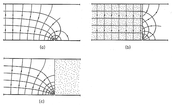
These potential distributions, and sketches of the associated fields, are illustrated in Fig. 6.6.9. Shown first is the uniform dielectric. Laplace's equation prevails throughout, even at the "interface." Far to the left, we know that the potential is linear in y, and hence represented by the equally spaced parallel straight lines. These lines must end at other points on the bounding surface having the same potential. The only place where this is possible is in the singular region at the origin where the potential makes an abrupt change from V to 0. These observations provide a starting point in sketching the field lines.
Figure 6.6.9 Equipotentials and field lines for configuration of Fig. 6.6.8. (a) Fringing for uniform dielectric. (b) With high permittivity material between capacitor plates, field inside tends to become tangential to the interface and uniform throughout the region to the left. (c) With high permittivity material outside the region between the capacitor plates, the field inside tends to be perpendicular to the interface. Shown next is the field distribution in the limit where the permittivity between the capacitor plates (to the left) is very large compared to that outside. As is clear by taking the limit
a /
b
0 in (36), the field inside the capacitor tends to be uniform right up to the edge of the capacitor. The dielectric effectively ducts the electric field. As far as the field inside the capacitor is concerned, there tends to be no normal component of E.
In the opposite extreme, where the region to the right has a high permittivity compared to that between the capacitor plates, the electric field inside the capacitor tends to approach the interface normally. As far as the potential to the left is concerned, the interface is an equipotential.
In Chap. 9, we find that magnetization and polarization phenomena are analogous. There we delve further into approximations on magnetic field distributions in the presence of magnetizable materials that can just as well be used to understand systems of piece-wise uniform dielectrics.


