Conductor configurations are often made up from materials that are uniformly conducting. The conductivity is then uniform in the subregions occupied by the different materials but undergoes step discontinuities at interfaces between regions. In the uniformly conducting regions, the potential obeys Laplace's equation, (7.2.5),

while at the interfaces between regions, the continuity conditions require that the normal current density and tangential electric field intensity be continuous, (7.2.9) and (7.2.10).


Analogy to Fields in Linear Dielectrics
If the conductivity is replaced by the permittivity, these laws are identical to those underlying the examples of Sec. 6.6. The role played by D is now taken by J. Thus, the analysis for the following example has already been carried out in Sec. 6.6.
Example 7.5.1. Conducting Circular Rod in Uniform Transverse Field
A rod of radius R and conductivity
b is immersed in a material of conductivity
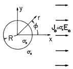
a, as shown in Fig. 7.5.1. Perhaps imposed by means of plane parallel electrodes far to the right and left, there is a uniform current density far from the cylinder.
Figure 7.5.1 Conducting circular rod is immersed in a conducting material supporting a current density that would be uniform in the absence of the rod. The potential distribution is deduced using the same steps as in Example 6.6.2, with
a

a and
b

b. Thus, it follows from (6.6.21) and (6.6.22) as
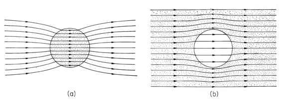
and the lines of electric field intensity are as shown in Fig. 6.6.6. Note that although the lines of E and J are in the same direction and have the same pattern in each of the regions, they have very different behaviors where the conductivity is discontinuous. In fact, the normal component of the current density is continuous at the interface, and the spacing between lines of J must be preserved across the interface. Thus, in the distribution of current density shown in Fig. 7.5.2, the lines are continuous. Note that the current tends to concentrate on the rod if it is more conducting, but is diverted around the rod if it is more insulating.
Figure 7.5.2 A surface charge density resides at the interface between the conducting media of different conductivities. This surface charge density acts as the source of E on the cylindrical surface and is identified by (7.2.17).Distribution of current density in and around the rod of Fig. 7.5.1. (a)
b

a. (b)
a

b.
Inside-Outside Approximations
In exploiting the formal analogy between
fields in linear dielectrics and in Ohmic conductors, it is important
to keep in mind the very different physical phenomena being described.
For example, there is no conduction analog to the free space
permittivity  o. There is no minimum value of the
conductivity, and although
  can vary between a minimum of
  o
in free space and 1000
  o or more in special solids, the electrical
conductivity is even more widely varying. The ratio of the
conductivity of a copper wire to
that of its insulation exceeds 1021.
Because some materials are very good conductors while others are very good insulators, steady conduction problems can exemplify the determination of fields for large ratios of physical parameters. In Sec. 6.6, we examined field distributions in cases where the ratios of permittivities were very large or very small. The "inside-outside" viewpoint is applicable not only to approximating fields in dielectrics but to finding the fields in the transient EQS systems in the latter part of this chapter and in MQS systems with magnetization and conduction.
Before attempting a more general approach, consider the following example, where the fields in and around a resistor are described.
Example 7.5.2. Fields in and around a Conductor
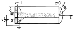
The circular cylindrical conductor of Fig. 7.5.3, having radius b and length L, is surrounded by a perfectly conducting circular cylindrical "can" having inside radius a. With respect to the surrounding perfectly conducting shield, a dc voltage source applies a voltage v to the perfectly conducting disk. A washer-shaped material of thickness
and also having conductivity
is connected between the perfectly conducting disk and the outer can. What are the distributions of
and E in the conductors and in the annular free space region?
Figure 7.5.3 Circular cylindrical conductor surrounded by coaxial perfectly conducting "can" that is connected to the right end by a perfectly conducting "short" in the plane z = 0. The left end is at potential v relative to right end and surrounding wall and is connected to that wall at z = -L by a washer-shaped resistive material. Note that the fields within each of the conductors are fully specified without regard for the shape of the can. The surfaces of the circular cylindrical conductor are either constrained in potential or bounded by free space. On the latter, the normal component of J, and hence of E, is zero. Thus, in the language of Sec. 7.4, the potential is constrained on S' while the normal derivative of
is constrained on the insulating surfaces S". For the center conductor, S' is at z = 0 and z = -L while S" is at r = b. For the washer-shaped conductor, S' is at r = b and r = a and S" is at z = -L and z = -(L +
). The theorem of Sec. 7.4 shows that the potential inside each of the conductors is uniquely specified. Note that this is true regardless of the arrangement outside the conductors.
In the cylindrical conductor, the solution for the potential that satisfies Laplace's equation and all these boundary conditions is simply a linear function of z.
Thus, the electric field intensity is uniform and z directed.
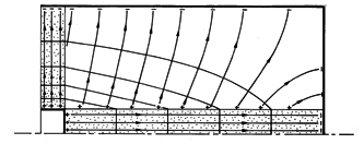
These equipotentials and E lines are sketched in Fig. 7.5.4. By way of reinforcing what is new about the insulating surface boundary condition, note that (6) and (7) apply to the cylindrical conductor regardless of its cross-section geometry and its length. However, the longer it is, the more stringent is the requirement that the annular region be insulating compared to the central region.
Figure 7.5.4 Distribution of potential and electric field intensity for the configuration of Fig. 7.5.3. In the washer-shaped conductor, the axial symmetry requires that the potential not depend on z. If it depends only on the radius, the boundary conditions on the insulating surfaces are automatically satsfied. Two solutions to Laplace's equation are required to meet the potential constraints at r = a and r = b. Thus, the solution is assumed to be of the form
The coefficients A and B are determined from the radial boundary conditions, and it follows that the potential within the washer-shaped conductor is
The "inside" fields can now be used to determine those in the insulating annular "outside" region. The potential is determined on all of the surface surrounding this region. In addition to being zero on the surfaces r = a and z = 0, the potential is given by (6) at r = b and by (9) at z = -L. So, in turn, the potential in this annular region is uniquely determined.
This is one of the few problems in this book where solutions to Laplace's equation that have both an r and a z dependence are considered. Because there is no
dependence, Laplace's equation requires that
The linear dependence on z of the potential at r = b suggests that solutions to Laplace's equation take the product form R(r)z. Substitution into (10) then shows that the r dependence is the same as given by (9). With the coefficients adjusted to make the potential
a(a, -L) = 0 and
a(b, -L) = v, it follows that in the outside insulating region
To sketch this potential and the associated E lines in Fig. 7.5.4, observe that the equipotentials join points of the given potential on the central conductor with those of the same potential on the washer-shaped conductor. Of course, the zero potential surface is at r = a and at z = 0. The lines of electric field intensity that originate on the surfaces of the conductors are perpendicular to these equipotentials and have tangential components that match those of the inside fields. Thus, at the surfaces of the finite conductors, the electric field in region (a) is neither perpendicular nor tangential to the boundary.
For a positive potential v, it is clear that there must be positive surface charge on the surfaces of the conductors bounding the annular insulating region. Remember that the normal component of E on the conductor sides of these surfaces is zero. Thus, there is a surface charge that is proportional to the normal component of E on the insulating side of the surfaces.
The order in which we have determined the fields makes it clear that this surface charge is the one required to accommodate the field configuration outside the conducting regions. A change in the shield geometry changes
a but does not alter the current distribution within the conductors. In terms of the circuit analogy used in Sec. 7.0, the potential distributions have been completely determined by the rod-shaped and washer-shaped resistors. The charge distribution is then determined ex post facto by the "distributed capacitors" surrounding the resistors.
The following demonstration shows that the unpaired charge density is zero in the volume of a uniformly conducting material and that charges do indeed tend to accumulate at discontinuities of conductivity.
 Demonstration 7.5.1. Distribution of Unpaired Charge
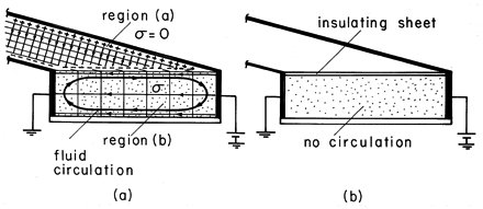
A box is constructed so that two of its sides and its bottom are plexiglas, the top is open, and the sides shown to left and right in Fig. 7.5.5 are highly conducting. It is filled with corn oil so that the region between the vertical electrodes in Fig. 7.5.5 is semi-insulating. The region above the free surface is air and insulating compared to the corn oil. Thus, the corn oil plays a role analogous to that of the cylindrical rod in Example 7.5.2. Consistent with its insulating transverse boundaries and the potential constraints to left and right is an "inside" electric field that is uniform.
Figure 7.5.5 Demonstration of the absence of volume charge density and existence of a surface charge density for a uniform conductor. (a) A slightly conducting oil is contained by a box constructed from a pair of electrodes to the left and right and with insulating walls on the other two sides and the bottom. The top surface of the conducting oil is free to move. The resulting surface force density sets up a circulating motion of the liquid, as shown. (b) With an insulating sheet resting on the interface, the circulating motion is absent. The electric field in the outside region (a) determines the distribution of charge on the interface. Since we have determined that the inside field is uniform, the potential of the interface varies linearly from v at the right electrode to zero at the left electrode. Thus, the equipotentials are evenly spaced along the interface. The equipotentials in the outside region (a) are planes joining the inside equipotentials and extending to infinity, parallel to the canted electrodes. Note that this field satisfies the boundary conditions on the slanted electrodes and matches the potential on the liquid interface. The electric field intensity is uniform, originating on the upper electrode and terminating either on the interface or on the lower slanted electrode. Because both the spacing and the potential difference vary linearly with horizontal distance, the negative surface charge induced on the interface is uniform.
Wherever there is an unpaired charge density, the corn oil is subject to an electrical force. There is unpaired charge in the immediate vicinity of the interface in the form of a surface charge, but not in the volume of the conductor. Consistent with this prediction is the observation that with the application of about 20 kV to electrodes having 20 cm spacing, the liquid is set into a circulating motion. The liquid moves rapidly to the right at the interface and recirculates in the region below. Note that the force at the interface is indeed to the right because it is proportional to the product of a negative charge and a negative electric field intensity. The fluid moves as though each part of the interface is being pulled to the right. But how can we be sure that the circulation is not due to forces on unpaired charges in the fluid volume?
An alteration to the same experiment answers this question. With a plexiglas sheet placed on the interface, it is mechanically pinned down. That is, the electrical force acting on the unpaired charges in the immediate vicinity of the interface is countered by viscous forces tending to prevent the fluid from moving tangential to the solid boundary. Yet because the sheet is insulating, the field distribution within the conductor is presumably unaltered from what it was before.
With the plexiglas sheet in place, the circulations of the first experiment are no longer observed. This is consistent with a model that represents the corn-oil as a uniform Ohmic conductor
1 See film Electric Fields and Moving Media, produced by the National Committee for Electrical Engineering Films and distributed by Education Development Center, 39 Chapel St., Newton, Mass. 02160. (For a mathematical analysis, see Prob. 7.5.3.)
In general, there is a two-way coupling between the fields in adjacent uniformly conducting regions. If the ratio of conductivities is either very large or very small, it is possible to calculate the fields in an "inside" region ignoring the effect of "outside" regions, and then to find the fields in the "outside" region. The region in which the field is first found, the "inside" region, is usually the one to which the excitation is applied, as illustrated in Example 7.5.2. This will be further illustrated in the following example, which pursues an approximate treatment of Example 7.5.1. The exact solutions found there can then be compared to the approximate ones.
Example 7.5.3. Approximate Current Distribution around Relatively Insulating and Conducting Rods
Consider first the field distribution around and then in a circular rod that has a small conductivity relative to its surroundings. Thus, in Fig. 7.5.1,
a

b. Electrodes far to the left and right are used to apply a uniform field and current density to region (a). It is therefore in this inside region outside the cylinder that the fields are first approximated.
With the rod relatively insulating, it imposes on region (a) the approximate boundary condition that the normal current density, and hence the radial derivative of the potential, be zero at the rod surface, where r = R.
Given that the field at infinity must be uniform, the potential distribution in region (a) is now uniquely specified. A solution to Laplace's equation that satisfies this condition at infinity and includes an arbitrary coefficient for hopefully satisfying the first condition is
With A adjusted to satisfy (13), the approximate potential in region (a) is
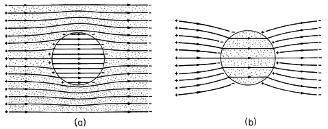
This is the potential in the exterior region, implying the field lines shown in Fig. 7.5.6a.
Figure 7.5.6 Distributions of electric field intensity around conducting rod immersed in conducting medium: (a) a

b; (b)
b

a. Compare these to distributions of current density shown in Fig. 7.5.2.
Now that we have obtained the approximate potential at r = R,
b = - 2Eo R cos (
), we can in turn approximate the potential in region (b).
The field lines associated with this potential are also shown in Fig. 7.5.6a. Note that if we take the limits of (4) and (5) where
a /
b
1, we obtain these potentials.
Contrast these steps with those that are appropriate in the opposite extreme, where
a /
b
1. There the rod tends to behave as an equipotential and the boundary condition at r = R is
a = constant = 0. This condition is now used to evaluate the coefficient A in (14) to obtain
This potential implies that there is a current density at the rod surface given by
The normal current density at the inside surface of the rod must be the same, so the coefficient B in (16) can be evaluated.
Now the field lines are as shown in Fig. 7.5.6b.
Again, the approximate potential distributions given by (17) and (19), respectively, are consistent with what is obtained from the exact solutions, (4) and (5), in the limit
a /
b
1.
In the following demonstration, a surprising electromechanical response has its origins in the charge distribution implied by the potential distributions found in Example 7.5.3.
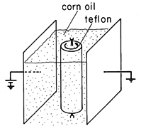
Demonstration 7.5.2. Rotation of an Insulating Rod in a Steady Current
In the apparatus shown in Fig. 7.5.7, a teflon rod is mounted at its ends on bearings so that it is free to rotate. It, and a pair of plane parallel electrodes, are immersed in corn oil. Thus, from the top, the configuration is as shown in Fig. 7.5.1. The applied field Eo = v/d, where v is the voltage applied between the electrodes and d is their spacing. In the experiment, R = 1.27 cm , d = 11.8 cm, and the applied voltage is 10-20 kV.
Figure 7.5.7 Rotor of insulating material is immersed in somewhat conducting corn oil. Plane parallel electrodes are used to impose constant electric field, so from the top, the distribution of electric field should be that of Fig. 7.5.6a, at least until the rotor begins to rotate spontaneously in either direction.
To explain this "motor," note that even though the corn oil used in the experiment has a conductivity of
a = 5 x 10-11 S/m, that is still much greater than the conductivity
b of the rod. Thus, the potential around and in the rod is given by (15) and (16) and the E field distribution is as shown in Fig. 7.5.6a. Also shown in this figure is the distribution of unpaired surface charge, which can be evaluated using (16).
Positive charges on the left electrode induce charges of the same sign on the nearer side of the rod, as do the negative charges on the electrode to the right. Thus, when static, the rod is in a posture analogous to that of a compass needle oriented backwards in a magnetic field. Its static state is unstable and it attempts to reorient itself in the field. The continuous rotation results because once it begins to rotate, additional fields are generated that allow the charge to leak off the cylinder through currents in the surrounding oil.
Note that if the rod were much more conducting than its surroundings, charges on the electrodes would induce charges of opposite sign on the nearer surfaces of the rod. This more familiar situation is the one shown in Fig. 7.5.6b.
The condition requiring that there be no normal current density at an insulating boundary can have a dramatic effect on fringing fields. This has already been illustrated by Example 7.5.2, where the field was uniform in the central conductor no matter what its length relative to its radius. Whenever we take the resistance of a wire having length L, cross-sectional area A, and conductivity
as being L/
A, we exploit this boundary condition.
The conduction analogue of Example 6.6.3 gives a further illustration of how an insulating boundary ducts the electric field intensity. With
a

a and
b

b, the configuration of Fig. 6.6.8 becomes the edge of a plane parallel resistor filled out to the edge of the electrodes by a material having conductivity
b. The fringing field then depends on the conductivity
a of the surrounding material.
The fringing field that would result if the entire region were filled by a material having a uniform conductivity is shown in Fig. 6.6.9a. By contrast, the field distribution with the conducting material extending only to the edge of the electrode is shown in Fig. 6.6.9b. The field inside is exactly uniform and independent of the geometry of what is outside. Of course, there is always a fringing field outside that does depend on the outside geometry. But because there is little associated current density, the resistance is unaffected by this part of the field.


