Porsche Anti-Theft System
A recent MIT grad just completed a very successful IPO of her Cambridge startup and celebrated by purchasing a new Porsche. Though the car has a built in anti-theft system, she is concerned since this is a standard factory unit and many people know how to disable it. So she's looking for someone to design and build a system with some hidden security features only you two will know about! Your job is to create a working prototype.
In this lab you will implement an anti-theft system that uses several interacting FSMs to process sensor inputs and generate the appropriate actuator control signals. This lab provides you with a design methodology that will be useful in future labs and your final project.
Procedure
- Read through the lab to understand the desired functionality, determine your approach and complete a design. Although not required, you may find it helpful to schedule a conference with a member of the course staff to review your design. This will help catch any major mistakes early in the process.
- Prototype your design using the FPGA. After you verify the anti-theft system's functionality get a member of the course staff to check you off. Be ready to demonstrate the functionality of your implementation and to answer the questions proposed in the Checkoff List section above.
Description of Anti-Theft System
Since your client is completely focused on her start-up, she wants an anti-theft system that's highly automated. The system is armed automatically after she turns off the ignition, exits the car (i.e., the driver's door has opened and closed) and T_ARM_DELAY has passed. If there is a passenger and both the driver's door and passenger's doors are open, the system arms itself after all the doors have been closed and T_ARM_DELAY has passed; that delay is restarted if a door is opened and reclosed before the alarm has been armed.
Once the system has been armed, opening the driver's door the system begins a countdown. If the ignition is not turned on within the countdown interval (T_DRIVER_DELAY), the siren sounds. The siren remains on as long as the door is open and for some additional interval (T_ALARM_ON) after the door closes, at which time the system resets to the armed but silent state. If the ignition is turned on within the countdown interval, the system is disarmed.
Always a paragon of politeness, your client opens the passenger door first if she's transporting a guest. When the passenger door is opened first, a separate, presumably longer, delay (T_PASSENGER_DELAY) is used for the countdown interval, giving her extra time to walk around to the driver's door and insert the key in the ignition to disarm the system.
There is a status indicator LED on the dash. It blinks with a two-second period when the system is armed. It is constantly illuminated either the system is in the countdown waiting for the ignition to turn on or if the siren is on. The LED is off is the system is disarmed.
So far this all is ordinary alarm functionality. But you're worried that a knowledgable thief might disable the siren and then just drive off with the car. So you've added an additional secret deterrent -- control of power to the fuel pump. When the ignition is off power to fuel pump is cut off. Power is only restored when first the ignition is turned on and then the driver presses both a hidden switch and the brake pedal simultaneously. Power is then latched on until the ignition is again turned off.
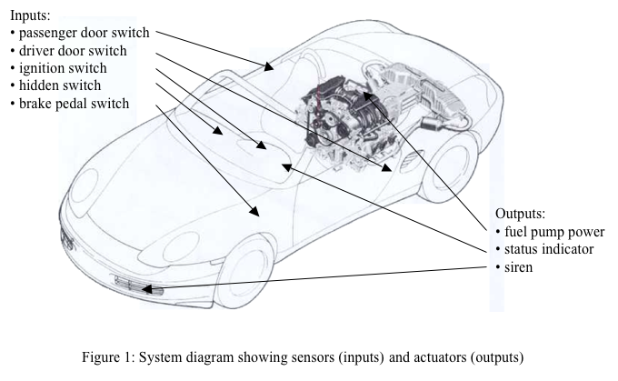
The diagram below lists all the sensors (inputs) and actuators (outputs) connected to the system.
The system timings are based on four parameters (in seconds): the delay between exiting the car and the arming of the alarm (T_ARM_DELAY), the length of the countdown before the alarm sounds after opening the driver's door (T_DRIVER_DELAY) or passenger door (T_PASSENGER_DELAY), and the length of time the siren sounds (T_ALARM_ON). The default value for each parameter is listed in the table below, but each may be set to other values using the Time_Parameter_Selector, Time_Value, and Reprogram signals. Time_Parameter_Selector switches specify the parameter number of the parameter to be changed. Time_Value switches are a 4-bit value representing the value to be programmed -- a value in seconds between 0 and 15. Pushing the Reprogram button tells the system to set the currently selected parameter to Time_Value. Note that your system should behave correctly even if one or more of the parameters is set to 0.
| Interval Name | Symbol | Parameter Number | Default Time (sec) | Time Value |
|---|---|---|---|---|
| Arming delay | T_ARM_DELAY | 00 | 6 | 0110 |
| Countdown, driver's door | T_DRIVER_DELAY | 01 | 8 | 1000 |
| Countdown, passenger door | T_PASSENGER_DELAY | 10 | 15 | 1111 |
| Siren ON time | T_ALARM_ON | 11 | 10 | 1010 |
Block Descriptions/Implementation
The following diagram illustrates a possible organization of your design into modules.
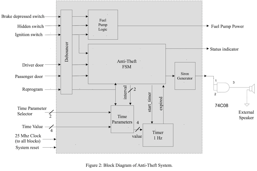
You should implement this lab by programming each module individually and then instantiating and connecting the modules together in the toplevel lab4_main.sv module. Then compile your implementation using Vivado, download it to the FPGA, and demonstrate its operation. Please use the following FPGA devices for the various sensors and actuators:
| Sensor/Actuator | Nexys 4 device |
|---|---|
| Hidden switch | btnu up button |
| Brake depressed switch | btnd down button |
| Driver door switch | btnl left button |
| Passenger door switch | btnr right button |
| Ignition switch | sw[14] |
| Time_parameter_selector | sw[5:4] |
| Time_value | sw[3:0] |
| Reprogram | btnc center button |
| Status light | led[0] |
| Fuel pump power | led[1] |
| Siren output | jb[0] |
| System reset | sw[15] |
Here's a more detailed description of each module:
- Debouncer
-
Your clocked state machine is controlled by several asynchronous
inputs that might be changed by the user at any time, potentially
creating a problem with metastability in the state registers if one of
the inputs changes too near a rising clock edge. In general
asynchronous inputs need to be synchronized to the internal clock
before they can be used by the internal logic.
synchronize.v
(available on the Handouts page of the course website) is a Verilog
implementation of a pulse synchronizer that can convert an
asynchronous signal to a synchronous one with acceptably low
probability of metastability in the synchronous signal.
A second problem arises from the mechanical "bounce" inherent in switches: as a metal contact opens and closes it may bounce a couple of times, creating a sequence of on/off transitions in rapid succession. So you need to use debouncing circuitry to filter out these unwanted transitions. debounce.v (available on the Handouts page of the course website) is a Verilog implementation of a digital retriggerable one-shot that requires that an input transition be stable for 0.01sec before reporting a transition on its output. This module happens to produce a synchronous output, so a separate synchronizer is not required. You should use an instance of the debounce module to debounce any switch inputs you use in your design.
- Time Parameters
-
The time parameters module stores the four different time parameter
values. The module acts like a 4-location memory that's initialized
with default values at power on, but may be reprogrammed by the user
at any time. Using the 2-bit Interval signal, the Anti-theft FSM
selects one of the four parameters to be used by the Timer module.
On power on, the parameters should be set to the default values specified above. However the user may modify any of the values by manipulating Time_Parameter_Selector (2 bits), Time_Value (4 bits), and Reprogram. Whenever a parameter is reprogrammed, the FSM should be reset to its ARMED state (after which it may transition immediately to another state depending on the sensor inputs).
- Timer
- The timer counts down the number of seconds specified by the Time Parameter module. It initializes its internal counter to the specified Value when Start_Timer is asserted and decrements the counter when one_hz_enable is asserted. When the internal counter reaches zero, the Expired signal is asserted and the countdown halts until Start_Timer is once again asserted. Within timer is the divider that converts the 25MHz master clock into an one_hz_enable signal that's asserted for just 1 cycle out of every 25,000,000 cycles (i.e., once per second). The one_hz_enable is used by the Timer module and for making the LED blink with a two-second period. The divider needs to reset when Start_Timer is asserted (see Timer module below) so that the first one_hz_enable after the timer starts to count comes a full second after the timer has been started.
- Anti-theft FSM
-
This finite state machine controls the sequencing for the system. The
system has four major modes of operation:
- Armed. The status indicator should be blinking with a two-second period; the siren is off. If the ingition switch is turned on go to Disarmed mode, otherwise when a door opens start the appropriate countdown and go to Triggered mode. This is the state the FSM should have when the system is powered on.
- Triggered. The status indicator light should be constantly on; the siren is off. If the ignition switch is turned on, go to Disarmed mode. If the countdown expires before the ignition is turned on, go to Sound Alarm Mode.
- Sound Alarm. The status indicator light and siren should be constantly on. The alarm should continue to sound until either T_ALARM_ON seconds after all the doors have closed (at which point go to Armed mode) or the ignition switch is turned on (at which point go to Disarmed mode).
- Disarmed. The status indicator light and siren should be off. Wait until the ignition switch is turned off, followed by the driver's door opening and closing, then after T_ARM_DELAY seconds go to Armed mode.
Note that more than one FSM state may be needed to implement the required functionality of each mode, i.e, your state transition diagram will have many more than 4 states.
- Fuel Pump Logic
- This simple FSM controls the power to the fuel pump. Power is disabled when the ignition switch is turned off and only reenabled when the appropriate sequence of sensor values is received (see description above).
- Siren Generator
- This module generates an audio-frequency square wave (i.e., a
sequence of alternating 0's and 1's) that can be used to drive an
external speaker. At a minimum your generator should alternate
at couple of second intervals between a 440Hz tone and a 880Hz tone.
But fancier effects are possible -- see below.
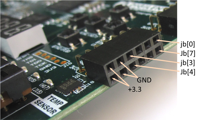
The IO pins cannot drive the speaker directly. We will use a 74HC08 as a driver. The speaker, cables, headers and protoboard are available on the staff bench. Using a male to male wire, connect the output of the siren generator to the jb[0] output of the FPGA, which appears on a connector on the right side of the board. Wire up a protoboard and connect jb[0] to pins 1 and 2 of the 74HC08 AND gate.
Check and make sure pin 14 is attached to 3.3V and pin 7 is attached to gound. Attach the speaker to pin 3 of the AND gate and ground. In this application, the AND gate is used to drive the speaker. The 74HC08 and speaker are operated way out of spec (and abused) - not recommended as an engineering design - but okay for lab use. Note the average voltage for a 0 to 3.3 volt square wave is 1.65V. Speakers should have an average voltage of zero! Another bad enginering practice. After the lab is checked off return the speaker assembly for other students to use.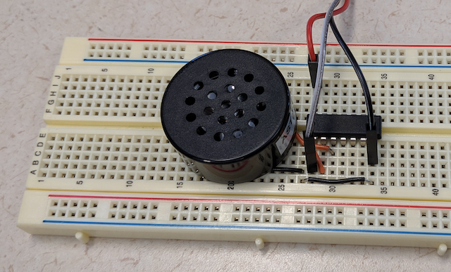
You're anxious to make a good impression on your client in the hopes of getting the design commissions (and earning an extra point on the lab). So once you've implemented the basic functionality described above, create a different sound effect with your Siren Generator. Some ideas:
- Alternate between a 440/880 Hz. [Value: 7 points]
- Produce a warbling tone (rapidly switch between a couple of frequencies). [Value: 7.5 points]
- Sweep the frequency of the audio tone from 440Hz to 880Hz (or Vice versa) and then repeat. Produces a repeating rising/falling tone instead just alternating between the two frequencies. [Value: 8 points - full credit]
- Create VGA graphics using the 25MHz clock for 640x480 graphics and display a green circle for disarm, blue for waiting, red for armed and flashing red for siren. [Value: 8 points - full credit]
- Challenge: Display the time with font ROMs and VGA graphics. A 8 bit 48x48 character COE file with the digits 0-9 is available here. The first 2304 (48x48) lines in the rom is the number zero. [Value: 9 points - one extra bonus point]
Getting Started
At this point, you should be sufficiently proficient to create your own project files. To get started, download the default xdc file. Uncomment the required I/O ports in the xdc file. Create a new project and using the Clock Wizard from the IP Catalog, generate a 25MHz clock. It is useful to make a simple project such as controlling a LED with a switch to verify the process. It may be useful to have additional switches and leds available to help with debugging. You will need the seven segment display to display the timer values. Name your top level file lab4_main.sv.
One of the most difficult module for this lab is the timer module. The timer module must be able to handle any value from 0-15 seconds. During countdown (or if you choose count up) it must be able to be restarted. For a value of zero (a valid input), expire is asserted at the next clock cycle after start_timer. We recommend using a pulse to start the timer and output a one cycle pulse for expire. Other approaches have worked but with some difficulty. There is a sample starter Verilog sample_tb.sv testbench and sample.sv Verilog module.
The waveform below shows a timer module that meets all the requirements for the car alarm. A five second timer is started, re-started near the 3 second mark and times down to zero. Another five second timer is started followed by a zero second timer. Note for this simulation, the "one Hz" clock is only 4 clock cycles and not millions. For simulation, it is not necessary to be real time.
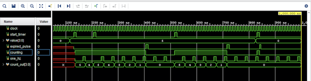
The signals counting and count_out are used to debug the timer and not required for operation. Here is the timer_tb.sv test bench used to run the simulation shown above and empty timer.sv Verilog module. .
Recommended Process
You can shorten your development time by building a test-bench for each module of your design and then the overall test-bench to verify the expected behavior of the system on several sequences of inputs that you expect to test on a real FPGA. Once the system passes these tests you can proceed to the implementation on the FPGA.
For Checkoff 1, show a simulation for your timer restarted midway through and with a time value of zero. Your timer simulation need not match exactly the waveform shown but your timer must be able to restart while counting and perform as specify with a timer value of zero. You can use our testbench or create your own. We have not provided other test benches since they are highly dependent on the design. Getting the timer right is an integral part of the car alarm.
For debug on the FPGA you have several options. Use the 8 seven segment display from lab 3 to show state and time information. You will need the display to show that your timer is working correctly. Use one digit to show the current state of the FSM, another digit to indicate currently selected time parameter, yet another digit to show the current value of the timer's module internal counter, etc. You'll want to use this handy module for displaying debugging info for all your designs!
Using the Integrated Logic Analyzer is very useful in debugging your design. Consider using it if you are stuck. (See lab 3.) Viewing real time waveforms with periods of seconds and sampling at megahertz clock speeds is not feasible. In this case, "speed up" the one hertz clock by reducing the divider to 10 or so.