|
|
|

for 6.111 Introduction to Digital Systems
6.111 home → Labkit home → Audio Input and Output
Audio Input and Ouput
by Nathan IckesIntroduction
The labkit's AC'97 audio codec can record and playback high-quality stereophonic sound. (AC'97 is an Intel standard for PC audio systems.) The codec's ADCs and DACs operate at a 48kHz sample rate, with 18 bits of precision.
Creating Simple Beeps
The easiest way to generate alert beeps and other simple tones is to use the FPGA to generate a digital squarewave on the "beep" input to the audio codec. As long as the reset pin of the codec is held low, the beep input is feed directly to the line-output jacks (but not the headphone jack): no configuration of the codec is necessary.
AC'97 Frames
AC'97 is a serial interface: data is transmitted to and from the codec one bit at a time. On every cycle of the AC'97 bit clock, one bit of data is transfered from the AC'97 controller (the FPGA) to the codec over the SDATA_OUT wire, and one bit of data is transfered from the codec to the FPGA over the SDATA_IN wire.
The constant streams of data passing between the codec and the FPGA are divided into frames. The bit clock is generated by the codec, and runs at 12.288MHz. There are 256 bits per frame, so 48,000 frames are sent per second. Each frame sent to the codec provides one 20-bit sample for each of the DACs in the codec, and each frame sent by the codec provides one 20-bit sample from each of the codec's ADCs.
Frames are divided into twelve slots of 20 bits each, plus a 16-bit tag field, which serves as the frame header. The start of each frame is indicated by a rising edge of the SYNC signal. The SYNC signal goes high one clock cycle before the first bit of a frame, and goes low at the same time as the last bit of the tag field is sent. (See the LM4550 datasheet for a more precise timing diagram.)
AC'97 frame format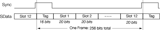
The bits in the tag slot indicate which, if any, of the other slots in the frame are valid. The tag bits have the following meanings.
- Bit 15 (the first bit transmitted) is a valid flag for the entire frame: if this bit is zero, the entire frame is invalid.
- Bits 14-3 are valid flags for the individual slots in the frame. Bit 14 corresponds to slot 1, bit 13 to slot 2, and so on. A one in the appropriate bit field indicates that the slot data is valid in this frame.
- Bit 2 is reserved, and should always be zero.
- Bits 1 and 0 are used to address the frame to a particular codec in some multi-codec systems. Since the labkit only has one codec, these bits should both be zero.
The LM4550 codec does not implement all of the features defined in the AC'97 specification, and hence does not use all twelve of the available slots. In a frame sent to the codec, the slots are used as follows.
- Slots 1 and 2 are used to read and write to configuration registers in the codec.
- Slot 3 is used to send PCM data to the left channel DAC.
- Slot 4 is used to send PCM data to the right channel DAC.
- Slots 6 through 8 are used only when multiple LM4550 codecs are used together to implement a surround sound system. (Not possible with the labkit hardware.)
The slots in a frame sent by the codec are used in the following manner.
- Slots 1 and 2 are used to indicate the status of the codec and to read the value of codec configuration registers.
- Slot 3 is used to send PCM data from the left channel ADC.
- Slot 4 is used to send PCM data from the right channel ADC.
The LM4550 is an 18-bit codec, so only the 18 most significant bits of slots 3 and 4 are used by the DACs and ADCs. PCM data for the DACs or from the ADCs is transmitted MSB first, in twos-complement form.
Codec Configuration Registers
The codec contains a number of registers which are used to control things like output volume, or to select the input source to be sampled by the ADCs (line inputs or microphone). Reading and writing to these configuration registers is done using slots 1 and 2 of the AC'97 frame.
A register may be written by sending a frame to the codec in which slots 1 and 2 are valid. In slot 1, bit 19 must be cleared to indicate that a register is to be written, and bits 18 through 12 are used to specify the address of the register to write. The 16 MSBs of slot 2 hold the data to be written to the specified register.
To read a register, a frame is sent to the codec in which bit 19 of slot 1 is set. Bits 18 through 12 again indicate which register is to be written. Slot 2 should be valid, but contain all zeros. In the next frame sent by the codec, slot 2 will contain the value read from the specified register.
Most applications will have to write to at least some of the following registers.
- The master volume register (0x02) controls the volume level on the line-level output jacks. Volume is specified with separate 5-bit values for each of the left and right channels (with 00000 being the loudest setting) and a single mute bit. On reset, the mute bit is set. It must be cleared in order to get any sound out of the line-level outputs.
- The headphone volume register (0x04) controls the volume level on the headphone outputs, and works just like the master volume register. Again, the outputs are muted on reset.
- The record source select register (0x1A) selects which input source (line-level inputs or microphone) is sampled by the ADCs. The sources for the left and right channels can be set independently.
- The record gain register (0x1C) sets the amount by which the incoming audio is amplified before being sampled by the ADCs. In this case, setting a value of 1111 for a channel gives maximum gain. And, of course, there is another one of those pesky mute bits that must be cleared in order to record anything.
- The PCM gain register (0x18) sets the gain applied to the DAC outputs before feeding them into the output mixer. There is another mute bit here which must be cleared in order to get any sound from the DACs.
- The line-in volume (0x10) and microphone volume (0x0E) registers allow the line-level and microphone inputs to be fed directly into the output mixers, without digitizing these signals.
Example
The following example code implements an analog loopback test of the AC'97 codec. Three codec registers are written to enable the line-level and headphone outputs, and to route the line-level inputs into the output mixer. The audio signal is never digitized: this example only illustrates how to generate AC'97 frames, and how to write to codec registers.
- Verilog source code (includes
labkit.v):audioloopback.v - The standard constraints file:
labkit.ucf
More Information
- The AC'97 specification is available on Intel's audio webpage.
- Datasheet for the LM4550
MIT 6.111 Introduction to Digital Systems, Updated March 06, 2007