Visual Prosthesis
C. The use of implanted electrode arrays
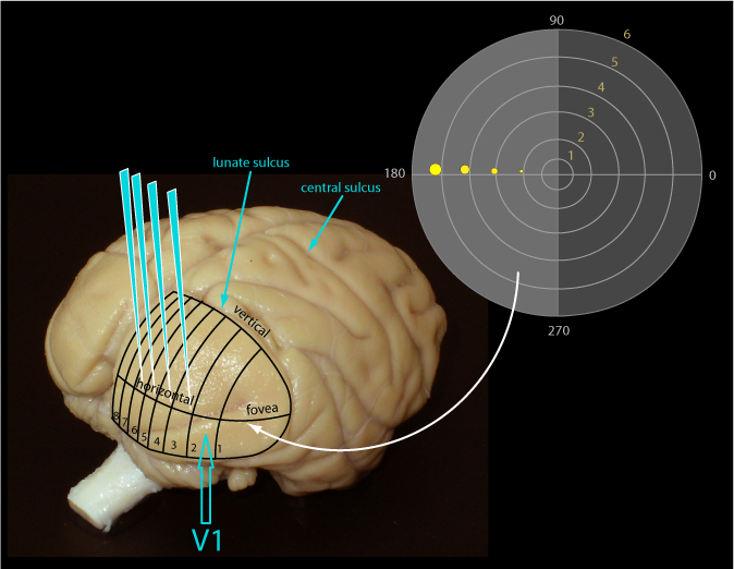
Figure 2 shows this arrangement in the rhesus monkey whose area V1 for central vision is lissencephalic which makes it relatively easy to record and stimulate it and to comprehend its layout. Shown in Figure 2 is how the left visual field is laid out on the surface of area V1. Four electrodes are shown placed at 2, 3, 4, and 5 degrees of eccentricity. The size of the receptive fields for each site is depicted on the right in the form of yellow disks: the receptive fields near the fovea are very small and grow progressively larger with increasing eccentricity.