

Ogg Vorbis I format specification: codec setup and packet decode
Last update to this document: July 18, 2002
Overview
This document serves as the top-level reference document for the
bit-by-bit decode specification of Vorbis I. This document assumes a
high-level understanding of the Vorbis decode process, which is
provided in the document Ogg Vorbis I
format specification: introduction and description. Ogg Vorbis I format specification:
bitpacking convention covers reading and writing bit fields from
and to bitstream packets.
Header decode and decode setup
A Vorbis bitstream begins with three header packets. The header
packets are, in order, the identification header, the comments header,
and the setup header. All are required for decode compliance. An
end-of-packet condition during decoding the first or third header
packet renders the stream undecodable. End-of-packet decoding the
comment header is a non-fatal error condition.
Common header decode
Each header packet begins with the same header fields
  1) [packet_type] : 8 bit value
  2) 0x76, 0x6f, 0x72, 0x62, 0x69, 0x73: the characters 'v','o','r','b','i','s' as six octets
Decode continues according to packet type; the identification header
is type 1, the comment header type 3 and the setup header type 5
(these types are all odd as a packet with a leading single bit of '0'
is an audio packet). The packets must occur in the order of
identification, comment, setup.
Identification Header
The identification header is a short header of only a few fields used
to declare the stream definitively as Vorbis, and provide a few externally
relevant pieces of information about the audio stream. The
identification header is coded as follows:
 1) [vorbis_version] = read 32 bits as unsigned integer
 2) [audio_channels] = read 8 bit integer as unsigned
 3) [audio_sample_rate] = read 32 bits as unsigned integer
 4) [bitrate_maximum] = read 32 bits as signed integer
 5) [bitrate_nominal] = read 32 bits as signed integer
 6) [bitrate_lower] = read 32 bits as signed integer
 7) [blocksize_0] = 2 exponent (read 4 bits as unsigned integer)
 8) [blocksize_1] = 2 exponent (read 4 bits as unsigned integer)
 9) [framing_flag] = read one bit
[vorbis_version] is to read '0' in order to be compatible
with this document. Both [audio_channels] and
[audio_rate] must read greater than zero. Allowed final
blocksize values are 64, 128, 256, 512, 1024, 2048, 4096 and 8192 in
Vorbis I. [blocksize_0] must be less than or equal to
[blocksize_1]. The framing bit must be nonzero. Failure to
meet any of these conditions renders a stream undecodable.
The bitrate fields above are used only as hints. The nominal bitrate
field especially may be considerably off in purely VBR streams. The
fields are meaningful only when greater than zero.
- All three fields set to the same value implies a fixed rate, or tightly bounded, nearly fixed-rate bitstream
- Only nominal set implies a VBR or ABR stream that averages the nominal bitrate
- Upper and or lower set implies a VBR bitstream that obeys the bitrate limits
- None set indicates the encoder does not care to speculate.
Comment Header
Comment header decode and data specification is covered in Ogg Vorbis I format specification: comment field
and header specification.
Setup Header
Vorbis codec setup is configurable to an extreme degree:
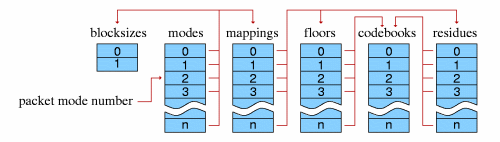
The setup header contains the bulk of the codec setup information
needed for decode. The setup header contains, in order, the lists of
codebook configurations, time-domain transform configurations
(placeholders in Vorbis I), floor configurations, residue
configurations, channel mapping configurations and mode
configurations. It finishes with a framing bit of '1'. Header decode
proceeds in the following order:
codebooks
- [vorbis_codebook_count] = read eight bits as unsigned integer and add one
- Decode [vorbis_codebook_count] codebooks in order as defined
in the codebook specification
document. Save each configuration, in order, in an array of
codebook configurations [vorbis_codebook_configurations].
time domain transforms
These hooks are placeholders in Vorbis I. Nevertheless, the
configuration placeholder values must be read to maintain bitstream
sync.
- [vorbis_time_count] = read 6 bits as unsigned integer and add one
- read [vorbis_time_count] 16 bit values; each value should be zero. If any other values is nonzero, this is an error condition and the stream is undecodable.
floors
Vorbis uses two floor types; header decode is handed to the decode
abstraction of the appropriate type.
- [vorbis_floor_count] = read 6 bits as unsigned integer and add one
- For each of [vorbis_floor_count] floor numbers:
- read the floor type; vector [vorbis_floor_types] element [i] = read 16 bits as unsigned integer
- If the floor type is zero, decode the floor configuration as defined in the floor type 0 specification document; save this configuration in slot [i] of the floor configuration array [vorbis_floor_configurations].
- If the floor type is one, decode the floor configuration as defined in the floor type 1 specification document; save this configuration in slot [i] of the floor configuration array [vorbis_floor_configurations].
- If the the floor type is greater than one, this stream is undecodable; ERROR CONDITION
residues
Vorbis uses three residue types; header decode of each type is identical.
- [vorbis_residue_count] = read 6 bits as unsigned integer and add one
- For each of [vorbis_residue_count] residue numbers:
- read the residue type; vector [vorbis_residue_types] element [i] = read 16 bits as unsigned integer
- If the residue type is zero, one or two, decode the residue configuration as defined in the residue specification document; save this configuration in slot [i] of the residue configuration array [vorbis_residue_configurations].
- If the the residue type is greater than two, this stream is undecodable; ERROR CONDITION
mappings
Mappings are used to set up specific pipelines for encoding
multichannel audio with varying channel mapping applications. Vorbis I
uses a single mapping type (0), with implicit PCM channel mappings.
- [vorbis_mapping_count] = read 6 bits as unsigned integer and add one
- For each [i] of [vorbis_mapping_count] mapping numbers:
- read the mapping type: 16 bits as unsigned integer. There's no reason to save the mapping type in Vorbis I.
- If the mapping type is nonzero, the stream is undecodable
- If the mapping type is zero:
- read 1 bit as a boolean flag
- if set, [vorbis_mapping_submaps] = read 4 bits as unsigned integer and add one
- if unset, [vorbis_mapping_submaps] = 1
- read 1 bit as a boolean flag; if set, square polar channel mapping is in use:
- [vorbis_mapping_coupling_steps]= read 8 bits as unsigned integer and add one
- for [j] each of [vorbis_mapping_coupling_steps] steps:
- vector [vorbis_mapping_magnitude] element [j]= read ilog([audio_channels]) bits as unsigned integer
- vector [vorbis_mapping_angle] element [j]= read ilog([audio_channels]) bits as unsigned integer
- the numbers read in the above two steps are channel numbers representing the channel to treat as magnitude and the channel to treat as angle, respectively. If any of angle channel equals magnitude channel, magnitude channel is greater than [audio_channels]-1, or angle channel is greater than [audio_channels]-1, the stream is undecodable.
- read 2 bits (reserved field); if the value is nonzero, the stream is undecodable
- if [vorbis_mapping_submaps] is greater than one, we read channel multiplex settings. For each [j] of [audio_channels] channels:
- vector [vorbis_mapping_mux] element [j] = read 4 bits as unsigned integer
- if the value is greater than the highest numbered submap, this in an error condition rendering the stream undecodable
- for each submap [j] of [vorbis_mapping_submaps] submaps, read the floor and residue numbers for use in decoding that submap:
- read and discard 8 bits (the unused time configuration placeholder)
- read 8 bits as unsigned integer for the floor number; save in vector [vorbis_mapping_submap_floor] element [j]
- verify the floor number is not greater than the highest number floor configured for the bitstream. If it is, the bitstream is undecodable
- read 8 bits as unsigned integer for the residue number; save in vector [vorbis_mapping_submap_residue] element [j]
- verify the residue number is not greater than the highest number residue configured for the bitstream. If it is, the bitstream is undecodable
- save this mapping configuration in slot [i] of the mapping configuration array [vorbis_mapping_configurations].
modes
- [vorbis_mode_count] = read 6 bits as unsigned integer and add oneFor each of [vorbis_mode_count] mode numbers:
- [vorbis_mode_blockflag] = read 1 bit
- [vorbis_mode_windowtype] = read 16 bits as unsigned integer
- [vorbis_mode_transformtype] = read 16 bits as unsigned integer
- [vorbis_mode_mapping] = read 8 bits as unsigned integer
- verify ranges; zero is the only legal value in Vorbis I for [vorbis_mode_windowtype] and [vorbis_mode_transformtype]. [vorbis_mode_mapping] must not be greater than the highest number mapping in use. Any illegal values render the stream undecodable.
- save this mode configuration in slot [i] of the mode configuration array [vorbis_mode_configurations].
- read 1 bit as a framing flag. If unset, a framing error occurred and the stream is not decodable.
After reading mode descriptions, setup header decode is complete.
Audio packet decode and synthesis
Following the three header packets, all packets in a Vorbis I stream
are audio. The first step of audio packet decode is to read and
verify the packet type; a non-audio packet when audio is expected
indicates stream corruption or a non-compliant stream. The decoder
must ignore the packet and not attempt decoding it to audio.
packet type, mode and window decode
- read 1 bit [packet_type]; check that packet type is 0 (audio)
- read ilog([vorbis_mode_count]-1) bits [mode_number]
- decode blocksize [n] is equal to [blocksize_0] if [vorbis_mode_blockflag] is 0, else [n] is equal to [blocksize_1]perform window selection and setup; this window is used later by the inverse MDCT:
- if this is a long window (the [vorbis_mode_blockflag] flag of this mode is set):
- read 1 bit for [previous_window_flag]
- read 1 bit for [next_window_flag]
- if [previous_window_flag] is not set, the left half
of the window will be a hybrid window for lapping with a
short block. See the
'Window' subheading of the specification introduction
document for an illustration of overlapping dissimilar
windows. Else, the left half window will have normal long
shape.
- if [next_window_flag] is not set, the right half of
the window will be a hybrid window for lapping with a short
block. See the
'Window' subheading of the specification introduction
document for an illustration of overlapping dissimilar
windows. Else, the left right window will have normal long
shape.
- if this is a short window, the window is always the same
short-window shape.
Vorbis windows all use the slope function y=sin(2*PI*sin^2(x/n)),
but dissimilar lapping requirements can affect overall shape. Window
generation proceeds as follows:
- [window_center] = [n] / 2
- [left_window_start]
- if ([vorbis_mode_blockflag] is set and [previous_window_flag] is not set) then
- [left_window_start] = [n]/4 - [blocksize_0]/4
- [left_window_end] = [n]/4 + [blocksize_0]/4
- [left_n] = [blocksize_0]/2
else
- [left_window_start] = 0
- [left_window_end] = [window_center]
- [left_n] = [n]/2
- if ([vorbis_mode_blockflag] is set and [next_window_flag] is not set) then
- [right_window_start] = [n]*3/4 - [blocksize_0]/4
- [right_window_end] = [n]*3/4 + [blocksize_0]/4
- [right_n] = [blocksize_0]/2
else
- [right_window_start] = [window_center]
- [right_window_end] = [n]
- [right_n] = [n]/2
- window from range 0 ... [left_window_start]-1 inclusive is zero
- for [i] in range [left_window_start] ... [left_window_end]-1, window([i]) = sin(2*PI*sin^2(([i]-[left_window_start]+.5)/[left_n]*PI/2))
- window from range [left_window_end] ... [right_window_start]-1 inclusive is one
- for [i] in range [right_window_start] ... [right_window_end]-1, window([i]) = sin(2*PI*sin^2(([i]-[right_window_start]+.5)/[right_n]*PI/2.+PI/2.))
- window from range [rigth_window_start] ... [n]-1 is zero
An end-of-packet condition up to this point should be considered an
error that discards this packet from the stream. An end of packet
condition past this point is to be considered a possible nominal
occurrence.
floor curve decode
From this point on, we assume out decode context is using mode number
[mode_number] from configuration array
[vorbis_mode_configurations] and the map number
[vorbis_mode_mapping] (specified by the current mode) taken
from the mapping configuration array
[vorbis_mapping_configurations].
Floor curves are decoded one-by-one in channel order.
For each floor [i] of [audio_channels]
- [submap_number] = element [i] of vector [vorbis_mapping_mux]
- [floor_number] = element [submap_number] of vector [vorbis_submap_floor]
- if the floor type of this floor (vector [vorbis_floor_types] element [floor_number]) is zero then decode the floor for channel [i] according to the floor 0 decode algorithm
- if the type of this floor is one then decode the floor for channel [i] according to the floor 1 decode algorithm
- save the needed decoded floor information for channel for later synthesis
- if the decoded floor returned 'unused', set vector [no_residue] element [i] to true, else set vector [no_residue] element [i] to false
An end-of-packet condition during floor decode shall result in packet
decode zeroing all channel output vectors and skipping to the
add/overlap output stage.
nonzero vector propagate
A possible result of floor decode is that a specific vector is marked
'unused' which indicates that that final output vector is all-zero
values (and the floor is zero). The residue for that vector is not
coded in the stream, save for one complication. If some vectors are
used and some are not, channel coupling could result in mixing a
zeroed and nonzeroed vector to produce two nonzeroed vectors.
for each [i] from 0 ... [vorbis_mapping_coupling_steps]-1
- if either [no_residue] entry for channel
([vorbis_mapping_magnitude] element [i]) or (channel
[vorbis_mapping_angle] element [i]) are set to false, then both
must be set to false. Note that an 'unused' floor has no decoded floor
information; it is important that this is remembered at floor curve
synthesis time.
residue decode
Unlike floors, which are decoded in channel order, the residue vectors
are decoded in submap order.
for each submap [i] in order from 0 ... [vorbis_mapping_submaps]-1
- [ch] = 0
- for each channel [j] in order from 0 ... [audio_channels]
- if channel [j] is in submap [i] (vector [vorbis_mapping_mux] element [j] is equal to [i])
- if vector [no_residue] element [j] is true
- vector [do_not_decode_flag] element [channels_in_bundle] is set
else- vector [do_not_decode_flag] element [channels_in_bundle] is unset
- increment [ch]
- [residue_number] = vector [vorbis_mapping_submap_residue] element [i]
- [residue_type] = vector [vorbis_residue_types] element [residue_number]
- decode [ch] vectors using residue [residue_number], according to type [residue_type], also passing vector [do_not_decode_flag] to indicate which vectors in the bundle should not be decoded. Correct per-vector decode length is [n]/2.
- [ch] = 0
- for each channel [j] in order from 0 ... [audio_channels]
- if channel [j] is in submap [i] (vector [vorbis_mapping_mux] element [j] is equal to [i])
- residue vector for channel [j] is set to decoded residue vector [ch]
- increment [ch]
inverse coupling
for each [i] from [vorbis_mapping_coupling_steps]-1 descending to 0
- [magnitude_vector] = the residue vector for channel
(vector [vorbis_mapping_magnitude] element [i])
- [angle_vector] = the residue vector for channel (vector
[vorbis_mapping_angle] element [i])
- for each scalar value [M] in vector [magnitude_vector] and the corresponding scalar value [A] in vector [angle_vector]:
- if ([M] is greater than zero)
- if ([A] is greater than zero)
- [new_M] = [M]
- [new_A] = [M]-[A]
else
- [new_A] = [M]
- [new_M] = [M]+[A]
else
- if ([A] is greater than zero)
- [new_M] = [M]
- [new_A] = [M]+[A]
else
- [new_A] = [M]
- [new_M] = [M]-[A]
- set scalar value [M] in vector [magnitude_vector] to [new_M]
- set scalar value [A] in vector [angle_vector] to [new_A]
dot product
For each channel, synthesize the floor curve from the decoded floor
information, according to packet type. Note that the vector synthesis
length for floor computation is [n]/2.
For each channel, multiply each element of the floor curve by each
element of that channel's residue vector. The result is the dot
product the floor and residue vectors for each channel; the produced
vectors are the length [n]/2 audio spectrum for each
channel.
One point is worth mentioning about this dot product; a common mistake
in a fixed point implementation might be to assume that a 32 bit
fixed-point representation for floor and residue and direct
multiplication of the vectors is sufficient for acceptable spectral
depth in all cases because it happens to mostly work with the current
Xiph.Org reference encoder.
However, floor vector values can span ~140dB (~24 bits unsigned), and
the audio spectrum vector should represent a minimum of 120dB (~21
bits with sign), even when output is to a 16 bit PCM device. For the
residue vector to represent full scale if the floor is nailed to
-140dB, it must be able to span 0 to +140dB. For the residue vector
to reach full scale if the floor is nailed at 0dB, it must be able to
represent -140dB to +0dB. Thus, in order to handle full range
dynamics, a residue vector may span -140dB to +140dB entirely within
spec. A 280dB range is approximately 48 bits with sign; thus the
residue vector must be able to represent a 48 bit range and the dot
product must be able to handle an effective 48 bit times 24 bit
multiplication. This range may be achieved using large (64 bit or
larger) integers, or implementing a movable binary point
representation.
inverse MDCT
Convert the audio spectrum vector of each channel back into time
domain PCM audio via an inverse Modified Discrete Cosine Transform
(MDCT). A detailed description of the MDCT is available in the paper
_The
use of multirate filter banks for coding of high quality digital
audio_, by T. Sporer, K. Brandenburg and B. Edler. The window
function used for the MDCT is the window determined earlier.
overlap_add
Windowed MDCT output is overlapped and added with the right hand data
of the previous window such that the 3/4 point of the previous window
is aligned with the 1/4 point of the current window (as illustrated in
the 'Window' portion of the
specification introduction document. The overlapped portion
produced from overlapping the previous and current frame data is
finished data to be returned by the decoder. This data spans from the
center of the previous window to the center of the current window. In
the case of same-sized windows, the amount of data to return is
one-half block consisting of and only of the overlapped portions. When
overlapping a short and long window, much of the returned range is not
actually overlap. This does not damage transform orthogonality. Pay
attention however to returning the correct data range; the amount of
data to be returned is:
window_blocksize(previous_window)/4+window_blocksize(current_window)/4
from the center (element windowsize/2) of the previous window to the
center (element windowsize/2-1, inclusive) of the current window.
Data is not returned from the first frame; it must be used to 'prime'
the decode engine. The encoder accounts for this priming when
calculating PCM offsets; after the first frame, the proper PCM output
offset is '0' (as no data has been returned yet).
output channel order
Vorbis I specifies only a channel mapping type 0. In mapping type 0,
channel mapping is implicitly defined as follows for standard audio
applications:
- one channel:
- the stream is monophonic
- two channels:
- the stream is stereo. channel order: left, right
- three channels:
- the stream is a 1d-surround encoding. channel order: left, center, right
- four channels:
- the stream is quadraphonic surround. channel order: front left, front right, rear left, rear right
- five channels:
- the stream is five-channel surround. channel order: front left, front center, front right, rear left, rear right
- six channels:
- the stream is 5,1 surround. channel order: front left, front center, front right, rear left, rear right, LFE
- greater than six channels:
- channel use and order is defined by the application
Applications using Vorbis for dedicated purposes may define channel
mapping as seen fit. Future channel mappings (such as three and four
channel Ambisonics) will make
use of channel mappings other than mapping 0.
 Ogg is a Xiph.org Foundation effort
to protect essential tenets of Internet multimedia from corporate
hostage-taking; Open Source is the net's greatest tool to keep
everyone honest. See About
the Xiph.org Foundation for details.
Ogg is a Xiph.org Foundation effort
to protect essential tenets of Internet multimedia from corporate
hostage-taking; Open Source is the net's greatest tool to keep
everyone honest. See About
the Xiph.org Foundation for details.
Ogg Vorbis is the first Ogg audio CODEC. Anyone may freely use and
distribute the Ogg and Vorbis specification, whether in a private,
public or corporate capacity. However, the Xiph.org Foundation and
the Ogg project (xiph.org) reserve the right to set the Ogg Vorbis
specification and certify specification compliance.
Xiph.org's Vorbis software CODEC implementation is distributed under a
BSD-like license. This does not restrict third parties from
distributing independent implementations of Vorbis software under
other licenses.
Ogg, Vorbis, Xiph.org Foundation and their logos are trademarks (tm)
of the Xiph.org Foundation. These
pages are copyright (C) 1994-2002 Xiph.org Foundation. All rights
reserved.