Monitoring the Solidification of Metal Castings
How the strand solidifies affects both the rate of production and the quality of the product. The strand solidifies from the outside in and exits the caster with a solidified shell around the outside of a still-molten core. How quickly that solidified shell thickens determines how quickly the strand can be extracted from the caster without breaking. How quickly the entire molten core becomes solid determines how soon the strand can be cut without leaking molten metal. And the location, shape, and movement of the "solidification front"--the point at which the liquid metal becomes solid--directly influence the formation of flaws such as voids, surface defects, and cracks. A monitor that could track the behavior of the solidification front in real time would enable manufacturers to control cooling rates and other operating conditions so as to run the continuous caster as quickly as possible while avoiding accidents and reducing defects in the products.
Developing a monitor that can be used on a moving, solidifying continuous casting in industry is a major challenge. During the past three years, Professor Jung-Hoon Chun and his Energy Laboratory coworkers have made significant progress toward that goal by working with metals solidifying in stationary molds--an approach known as "discrete casting" used by manufacturers to make final parts such as engine blocks. The interdisciplinary research project, dubbed "CastScan," involves Professor Chun, Dr. Nannaji Saka, Dr. Richard C. Lanza, Mark M. Hytros, and Imad M. Jureidini. The project also involves a consortium of interested industrial collaborators and sponsors.
Techniques for monitoring solidification in the industrial setting--whether for continuous or discrete casting--have their limitations. Various experimental techniques yield valuable information about the solidification process, but none is suitable for use in industry. Thermocouples inserted into the metal casting can directly measure temperature and thereby track the moving solidification front. But the presence of the thermocouples damages the part produced. Nondestructive methods involving sonic, infrared, and conventional X-ray imaging cannot handle the thick cross section of the typical manufactured strand and the high temperatures of the metals being cast. Computer models that simulate the solidification process produce useful information, but better experimental data are needed to refine and validate them.
Professor Chun and his colleagues have therefore been pursuing a new approach--one that combines high-energy radiation with computed tomography (CT), the technique used in taking medical images. Key to their approach is the behavior of high-energy electromagnetic radiation as it passes through metal. When a beam of high-energy X-rays or gamma rays encounters a metal object, photons in the beam penetrate the object; but not all make it through. Some are absorbed or scattered. How much reduction, or "attenuation," of the beam occurs depends on the density of the metal object. The density of a solid metal can be 4% to 12% higher than the density of the same metal in liquid form. As a result, the attenuation of a radiation beam differs depending on whether it has passed through the liquid or solid part of a solidifying metal. Taking attenuation measurements at many angles through a solidifying metal object--the scanning technique used in the medical procedure-- yields data that can form a CT image distinguishing solid from liquid.
In early experiments, the MIT researchers used their approach to locate the solidification front in a crucible of tin. Part of the tin was heated and part cooled to produce both liquid and solid regions and a stationary solidification front. They aimed a narrow beam of gamma rays from a radioisotope (cobalt-60) through the crucible of tin and onto a detector. The detector measured the incident photons over a certain time period and determined the amount of attenuation that occurred. The researchers then moved the crucible slightly so the beam entered it at an adjacent position. After taking measurements through many positions on that face of the crucible, they rotated the crucible slightly and repeated the scanning procedure. CT analysis of the entire set of attenuation measurements yielded an image that shows where the interfaces between the solid and liquid regions occur.
The experimental results confirmed the feasibility of the approach. However, collecting the data took fully 14 days! Moreover, the image produced was imprecise because temperatures inevitably fluctuate and the solidification front moves during such a long time period.
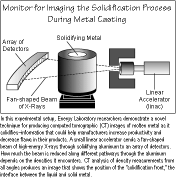
To solve those problems, the researchers turned to a different radiation source: a 6-MeV X-ray linear accelerator (linac). During a single second, the linac fires about 4 trillion photons through a square centimeter located a meter away--about a million times more than generated by the cobalt-60. The photons also have higher energy levels and can penetrate pieces of metal as much as 60 cm in thickness. The linac does not generate a continuous beam but instead emits 200 pulses of radiation per second. That pulsed operating mode allows the linac to be small in size but required the MIT team to specially adapt the data acquisition system for measuring the X-ray attenuation.
To further decrease the data acquisition time, the researchers use the
linac not with a single detector but with an array of 128 detectors. The
figure below shows the experimental setup. The high-energy X-rays exit
the linac in a fan-shaped beam. The photons pass along different pathways
through the metal object to different detectors, all at the same time.
The object still must be rotated within the beam, but moving it from one
place to another is unnecessary unless its dimensions exceed the width
of the fan beam. (The beam can also be focused into a "pencil" configuration.)

The researchers perform their experiments in the "CastScan Laboratory," which is located on the grounds of the Bates Linear Accelerator Center in Middleton, Massachusetts. They use a small, portable linac provided by the Idaho National Engineering and Environmental Laboratory. The team specially built the remainder of the setup, including a shielded room with 75-cm-thick concrete walls that houses the equipment. Unlike the cobalt-60, the linac does not emit harmful radiation when not in use; but shielding is still necessary to protect operators from radiation hazards.
The researchers have now demonstrated their new technique using aluminum, an important industrial metal with a melting point of 660oC as opposed to the 232oC of the pure tin used in the early studies. In this experiment, a pure aluminum casting almost 15 cm in diameter was melted in a cylindrical crucible placed inside a cylindrical furnace. Cool air was then passed down a tube immersed in the middle of the liquid aluminum, causing the aluminum to solidify. The furnace was completely rotated once per minute, during which time each detector took 2700 measurements. After every complete rotation the furnace was shifted to a new position and rotated again. This procedure yielded an image for every minute, each one based on density data averaged over two minutes. Thermocouples placed in the liquid independently measured temperature.
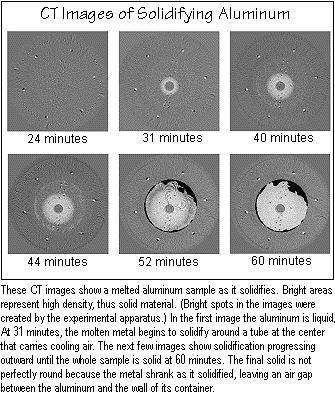
Using the images, the researchers have produced a movie that shows the
aluminum as it gradually solidifies over the course of an hour. The complete
movie is available on the World Wide Web at <http://castscan.mit.edu:80/castscan/solidifi.htm>.
Selected images are shown below. The dark circle in the center is the tube
of cool air. The light areas indicate high density, the solidified regions.
(Differences in density have been amplified by image enhancement techniques.)
The six bright spots are steel support rods. At 24 minutes, the aluminum
is still completely liquid. At 31 minutes, the metal begins to solidify
around the cooling tube, appearing as a bright ring at the center of the
image. The thermocouples now show up as small bright spots in the still-liquid
aluminum. The bright area at the center continues to expand as solidification
progresses outward. At 52 minutes, dark areas show the formation of an
air gap between the aluminum and the wall of the crucible--the result of
the metal's shrinking as it solidifies. The last figure shows the aluminum
in a completely solidified state.

The CT images unmistakably show the evolution of the solidification front. The position of the front matches the thermocouple measurements within 2 mm. The maximum and minimum intensities of the pixels in the images differ by 7%, as do the densities of solid and liquid aluminum. The locations and sizes of cavities created during solidification are clearly evident--information critical to improving the quality of cast parts.
While the data-acquisition time is dramatically shorter than in the cobalt-60 experiments, it is still too long for real-time industrial use. In addition, the technique cannot be used on continuous castings because of their size and geometry. To solve those problems, the researchers are developing a new method of analyzing the data. The method, called "partial view tomographic imaging," involves constructing a three-dimensional image based on scans from only one direction, so the casting need not be rotated. Based on known facts about the geometry, density, and other properties of the metal casting, a computer model calculates the location and shape of the solidification front after one second and compares its answer to measured data. If the outcomes do not match, the computer model alters its assumptions slightly and performs its calculation again. When the calculated and measured results match, the model moves to the next second and performs the iterative process again. Successful implementation of this approach should reduce the data acquisition time to as little as 1-3 seconds--well within the range needed for industrial use -- while making the monitor suited for use on continuous as well as discrete castings.
Another prerequisite to the monitor's commercial usefulness is its ability
to deal with alloys--combinations of pure metals and other elements that
yield high strength or other desirable properties. Alloys pose a particular
challenge because the different elements generally have different solidification
points. The solidification "front" therefore typically occurs within a
partially solidified area known as the "mushy zone." The researchers believe
that the linac-based system will prove sufficiently sensitive to detect
the gradual variations in density that occur within the mushy zone. Experiments
with aluminum alloys are now under way. The researchers are also making
plans to test their linac-based monitor on a continuous caster in a manufacturing
plant. Those field tests will show both the technical and economic viability
of using the monitor in the commercial industrial environment.