
April-June 1999 Issue
Measuring the Mechanical Properties of Materials
April-June 1999 Issue
Measuring the Mechanical Properties of Materials
![]() redicting how materials behave under stress is difficult, especially when only a small specimen or thin film is available for testing. One technique involves using an "indentor" to poke a probe into the material while accurately measuring the penetration depth and the force exerted. But analytical methods for inferring mechanical properties from such measurements are generally not reliable; and they cannot handle "graded" materials in which the composition varies with depth to provide variations of properties such as stiffness and resistance to excessive deformation. Now researchers affiliated with the Energy Laboratory have developed methods that perform such analyses in conjunction with a new generation of microindentors and nanoindentors. The indentor takes clear, continuous measurements of how penetration depth relates to applied force; and the analytical method translates those measurements into an unambiguous set of properties describing the specimen being tested. Based on this research, Instron Corporation is developing an instrument for analyzing homogeneous materials and is also incorporating the method for graded materials. This technology should make possible quick quality-control and materials inspections at manufacturing plants, remote inspections of surfaces in nuclear power plants, and development of damage-resistant graded materials for uses ranging from dental implants to tank armor. The MIT researchers are now using the technology to develop new surface coatings that are unusually resistant to cracking and damage.
redicting how materials behave under stress is difficult, especially when only a small specimen or thin film is available for testing. One technique involves using an "indentor" to poke a probe into the material while accurately measuring the penetration depth and the force exerted. But analytical methods for inferring mechanical properties from such measurements are generally not reliable; and they cannot handle "graded" materials in which the composition varies with depth to provide variations of properties such as stiffness and resistance to excessive deformation. Now researchers affiliated with the Energy Laboratory have developed methods that perform such analyses in conjunction with a new generation of microindentors and nanoindentors. The indentor takes clear, continuous measurements of how penetration depth relates to applied force; and the analytical method translates those measurements into an unambiguous set of properties describing the specimen being tested. Based on this research, Instron Corporation is developing an instrument for analyzing homogeneous materials and is also incorporating the method for graded materials. This technology should make possible quick quality-control and materials inspections at manufacturing plants, remote inspections of surfaces in nuclear power plants, and development of damage-resistant graded materials for uses ranging from dental implants to tank armor. The MIT researchers are now using the technology to develop new surface coatings that are unusually resistant to cracking and damage.
When engineers consider materials for specific applications, they need to know how those materials will behave when they are put into use and subjected to stress. One way to find out is by performing a pulling, or "tensile," test. A device grasps two ends of a specimen (generally in the form of a bar) and pulls it apart, simultaneously measuring the force exerted and the change in the specimen's length. Critical properties tested include how much a material stretches for a given pull and how much pulling it can take before it no longer springs back to its original shape when released. But with today's focus on micron-scale applications, many specimens of interest are too tiny to pull, or they occur as thin films adhered to a substrate. In such cases, engineers can use a technique called indentation, which involves poking the surface of the specimen with a sharp or blunt instrument, monitoring how depth changes with the force of the poke, and then deducing mechanical properties from those measurements. This technique requires little material--basically just the surface itself--and it can be used to test specific locations on a surface, thereby determining how properties vary from place to place.
But until recently, indentation could not determine how properties vary with depth--the capability needed by Professor Subra Suresh and his coworkers at MIT and the State University of New York at Stony Brook in their study of a broad range of novel engineering materials. For the past six years, they have been developing "graded" materials. Using a plasma torch, they spray molten particles of ceramics and metals onto a substrate, where they adhere and build up in layers. By gradually adjusting the ratio between the feedstocks, the researchers create a deposit in which one material predominates at the surface and the other gradually takes over with increasing depth. This approach avoids a sharp junction between two dissimilar materials and thus a weak bond. And the gradation that results provides practical advantages. For example, an excellent cutting tool can be made from a sharp but brittle material at the surface that gradually changes to a strong, less brittle material under the surface.
As Professor Suresh and his team began to produce novel graded coatings, they needed to measure the mechanical properties of their new materials. Indentation seemed a promising approach, but existing indentors had shortcomings. For one thing, methods used to deduce mechanical properties from an indentation test were not reliable and did not produce sufficiently detailed information on how behavior changes as stress increases. Moreover, the only means of characterizing the subsurface layers in a graded specimen was to grind off the surface and indent each layer as it became exposed. This procedure seemed a cumbersome and unreliable means of producing information the researchers needed both to optimize their materials and to predict what will happen if subsurface layers become exposed when the materials are in use, for example, through oxidation.
In 1995, the team began to develop new analytical methods for interpreting indentation measurements and a new indenting machine suited to their needs. While machines for indenting specimens existed, they did not have sufficient accuracy for probing at the micron scale of interest to the researchers. The indentors tended to be either too small to extend into the subsurface layers or too large to capture the details of the gradation. So Professor Suresh and Dr. Jorge Alcala designed and constructed an intermediate machine--a "microindentor"--that could help them develop and validate their analytical methods and examine the properties of their graded materials.
To gather the needed measurements, the indentor must penetrate the surface of a specimen under carefully controlled conditions. The tip of the indentor moves down until it touches the specimen. The indentation force gradually increases and then decreases, causing the tip first to dig into and then to rise out of the specimen. The force exerted and the depth of penetration are measured and recorded simultaneously and continuously during the loading and unloading process.
The figure below shows an idealized force-to-depth signal from a simple case: a homogeneous material. The upward-slanting section of the curve represents measurements taken during the loading process. Here the relationship between the downward force and the depth of the hole is predictable: the force is proportional to the depth squared. The highest point represents the turnaround point, thus the maximum force and maximum depth in the test. Subsequently, the curve moves downward as the force decreases (unloading), the diamond tip lifts upward, and the scar fills back in.
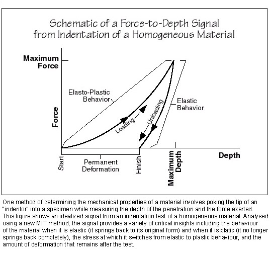
The loading portion of the curve reflects two types of behavior. Initially, the material is "elastic." If released, it would spring back to where it was originally. But at a certain level of force, the behavior of the material becomes "plastic." It gives way more easily and would no longer spring back if released because it has been permanently deformed by the indentor. During unloading, the material behaves elastically, springing back to fill in the hole. But because of the permanent deformation that occurred during loading, when the force drops to zero, the penetration depth does not. A dent remains.
Taken together, the loading and unloading portions of the signal contain information on the force at which the material's behavior switches from elastic to plastic, its response to changes in force under both conditions, and how much permanent deformation occurs. The signal thus serves as a kind of fingerprint that points to the specific set of mechanical properties of the material being tested. But quantifying those properties based on the raw signal is tricky. For one thing, the analytical modeling task is best approached as an "inverse" problem. Rather than using the material's properties to predict or explain the behavior, the analytical model should use the behavior to infer the properties--a more difficult procedure. Then there are added subtleties. For instance, depending on the nature of the surface, material surrounding the point of indentation can pile up or sink in, thereby changing the actual contact area between the indentor and the surface--a critical variable in the analytical procedure.
Dr. Antonios Giannakopoulos, working with Professor Suresh and Dr. Ole Jřrgensen, has now formulated theories that meet those challenges. The theories are in the form of interrelated mathematical equations that deduce all the mechanical properties simultaneously from the raw signal, taking into account details such as the effects of pile-up or sink-in. One theory is designed for signals from homogeneous materials, similar to the one shown in the figure above. The other is a revised form specially designed for graded materials. Based on the signal from a single indentation test, it calculates how the properties vary at different depths. In both cases, the theories work with quantities that are accurately measured in the experiments and produce unambiguous mathematical solutions.
The MIT researchers have filed patents on their microindentation device and analytical methods, and several patents have been licensed to Instron Corporation. Instron has developed a new microindentor along with software needed for analyzing homogeneous samples. Also included are step-by-step instructions so that users need no knowledge of the analytical method to perform the test. Instron is now incorporating the software that will interpret measurements from graded materials. Once available, that instrument will have many practical applications. For example, it can speed up quality-control inspections in automotive plants. Graded components will be characterized using a single indentation test rather than a series of tests interspersed with grinding--the current inspection method. It will also facilitate property measurements for ion-implanted surfaces used in microelectronic components. In other applications, the instrument could make possible the remote monitoring of potentially dangerous mixed and graded materials such as solid hazardous wastes and surfaces inside nuclear reactor containment structures. And it should help guide the development of better graded materials for applications that range from stronger, more durable dental and orthopedic implants to more shatter-resistant armor.
At MIT, Professor Suresh and his colleagues are continuing to improve the microindentor; and they have designed a special indentor that will also measure the electrical signal emitted when "piezoelectric" materials are deformed. (The coupling of mechanical and electrical responses in piezoelectric materials is useful in devices ranging from strain sensors to actuators, microphones, and ultrasonic generators.) And the microindentor is already proving a valuable tool as they look for better ways to create coatings using a plasma torch.
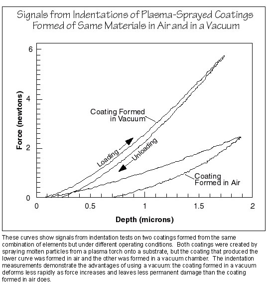
Their recent work in this area has focused on depositing coatings not in air but inside a chamber filled with an inert gas at low pressure--a setting that maintains the coatings at higher temperature during processing. Micrographs show that coatings formed in a vacuum are fairly uniform, while those formed in air still contain individual "splats" from the plasma torch, which may be prone to separating or sliding around under stress. Using the indentor, the researchers have been able to quantify the mechanical properties of their experimental coatings. The figure below shows signals from indentation tests of two coatings. Both were formed from the same combination of nickel, chromium, aluminum, and yttrium; but one was formed in air, the other inside the "vacuum" chamber. As suspected, the coating formed in the vacuum deforms much less rapidly with increasing force, and less deformation remains after the test. The researchers are continuing to use the microindentor to explore the relationship between processing conditions and the properties of the plasma-sprayed coatings that form.
Subra Suresh is the Richard P. Simmons Professor of Materials Science and Engineering. Jorge Alcala was a visiting scientist from 1995 to 1997 and Ole Jřrgensen was a visiting scientist in 1996, both in the Department of Materials Science and Engineering. Antonios Giannakopoulos is currently a research scientist in the same department. This research was supported by the University Research Consortium (URC) of the Idaho National Engineering and Environmental Laboratory, the US Department of Energy, the Office of Naval Research, and the National Science Foundation. The research on plasma processing of graded materials was supported by the URC. Further information can be found in references.