2.S97 Laser Cutter Tutorial
NOTE: Please ask a TA or mentor if you need any help!
Step 1: Generate .dxf file of the part you will be cutting out or rastering.
Step 2: Open CorelDRAW and create a new file. By default, CorelDRAW should set the dimensions of the file to be that of the laser cutter bed (32x18)
Step 3: Import your .dxf file into CorelDRAW by going to File>Import or by pressing Ctrl+I. Find the file and click Import.( Note that you can import multiple .dxf files at once.) Once Import is clicked, the following window will pop up:
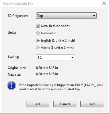
Make sure this window looks as shown here, though you must select the units to be the same units used in creating your .dxf file ensure that the scaling is 1:1. Once you press OK, you will then be able to place your part in corelDRAW by clicking within the design area. (Depending on which software you used to generate the .dxf, there may be extraneous text and a window will pop up asking about which font to use. Just press OK and then proceed to delete the text in CorelDRAW.)
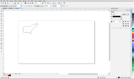
Step 4: Your CorelDRAW window should now look like this with your part in place of the part used in this example:
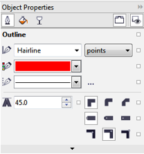
Now you must select the lines that you want the laser cutter to cut and set the line width to Hairline. This can be done in the Object Properties window on the right side of the above image. Below is what this window should look like:
Step 5: Set the color of lines you wish to be cut RED and regions you wish to be rastered BLACK.
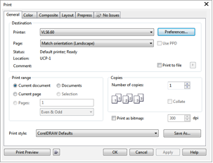
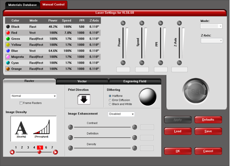
Step 6: Select File>Print or press Ctrl+P, and the following window will pop up. To change the power and speed settings of the laser cutter for your target material, select preferences.
You will then see a window that looks like this. You will then be able to map the various colors you used to the appropriate vector (cut through) or raster settings.
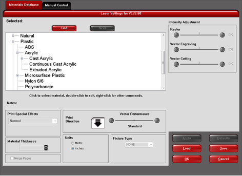
Select the Materials Database tab to bring up the following window, in which you should specify your material and material thickness. The program will automatically adjust power and speed for this material and thickness (but these parameters may need to be slightly adjusted for your job). Make sure to press Apply when finished.
Then press OK in both the preferences window and the print window and now were ready to move over to the software that controls the laser cutter.
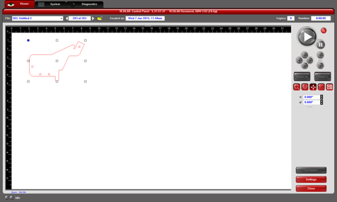
Step 7: Open the Universal Laser Systems Control Panel from the task bar. If youve done things correctly up to this point, your CorelDRAW file should automatically load into the control panel, as shown below. From here you can select the move tool on the right side of the window below to position your part in the laser bed. (Note that the top-left corner of the window corresponds with the back-left corner of the laser cutter bed itself.)
Step 8: Turn on the laser cutter using the control panel power button in the top-right corner of the window above.
Step 9:Place the material in the back-left corner of the laser bed, close the lid.
TURN THE EXHAUST ON!
Press the large play button in the control panel in the Universal Laser Systems Control Panel on the computer.
(Note you can press play with the lid open to see the path that the laser will take without actually turning the laser on. This is a good way to ensure that the path of the laser beam will be within the boundaries of you material.)
When you are done, TURN OFF the laser cutter using the red power button in the Universal Laser System Control Panel and turn off the exhaust.