

2.72 is a class that I took in the spring of 2012 that teaches the elements of mechanical design (power transmission, bolted joints, bearing selection, etc.) through the design and fabrication of a desktop-sized lathe. My group of 6 made a great lathe by adding small improvements on nearly every part of the old design. I was the FEA guru for my team, and although I primarily focused on flexure design, I made significant contributions to part selection and fabrication.
2.72 is not just about making a lathe, it's about learning about important elements of mechanical design. The lectures mostly occur in the first half of the course; the second half of the course is focused on making your lathe. This is because the knowledge that you need to model and evaluate the performance of your lathe is passed on before you make your device. In my opinion, this class was my favorite example of "Mens et Manus," (mind and hand) that is MIT's motto. There are some classes like 2.007 that are a lot of "Manus" and classes like 2.005 that are a lot of "Mens," but in this class, utilizing both is essential. You need to utilize the skills that you develop from theory classes and manufacturing techniques from hands on classes. Even the way you're tested is in both mind and hand: you're tested by hand via M-labs, you're tested by mind in reading quizzes, and you're tested in both with D-labs.
The first major milestone in 2.72 was making a spindle, shown below.
 The spindle is what holds the chuck. If you don't have a good spindle, you don't have a good lathe. The chuck has to be held on a drive shaft. That shaft has to be constrained by a set of bearings. The bearings have to allow the shaft to rotate while also being able to withstand high radial and axial loads. Tapered roller bearings are a great choice, but there are other options. The bearings have to be preloaded to work properly. The preload is very important, as it determines the stiffness, heat generated, runout and running torque. There is a careful balance for preload. A high preload increases stiffness and decreases runout which is great, but it also increases heat generated and running torque which is bad, so you have to preload the bearings just right.
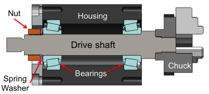 The preload is typically applied via a nut and Belleville washer. The preload can be measured through the use of a torque wrench, but a more direct measurement would be to measure the deflection of the nut and relate that to the spring force of the washer. Keep in mind that the Belleville washer stiffness is nonlinear with deflection and the washer is useless if it bottoms out (it becomes equivalent to a flat washer.)
Our group made a couple of changes to the spindle. First, we changed the way that we mounted the housing to the headstock. You can see this change in the pictures section, in the 3D pdf section and in the assembly video. We turned down the outside of the housing and made that flush (roughly speaking) with the front face of the headstock. This decreases the length of the cantilevered shaft that holds the chuck, which significantly increases its stiffness. It also effectively decreases the length of the the spindle that is hanging out the back of the headstock. This small change adds these benefits while keeping the same bearing spacing.
Our group was also the first group to challenge the issue of "thermal runaway." We were told that the bearings are facing the way that they are because it is thermally stable. If you were to flip the bearings, then all hell should break loose: the friction in the bearing rollers generates heat which gets transferred to the shaft, causing it to thermally expand. When the shaft expands, it increases the preload which generates more heat, which causes it to expand more which causes more preload which causes more heat, etc. It's a positive feedback loop that apparently should cause the lathe to blow up. We took images of the lathe with a thermal camera and we showed that the steel drive shaft and the aluminum housing were the same temperature. They both arrive at the same temperature and have roughly the same length, but the coefficient of thermal expansion of aluminum is roughly twice that of steel, so the aluminum housing is really expanding more than the shaft, which suggests that they've been mounting the bearings the wrong way for years! Ultimately we showed that since the heat gets dissipated to the environment, the thermal runaway isn't really an issue, it will just change the steady state temperature.
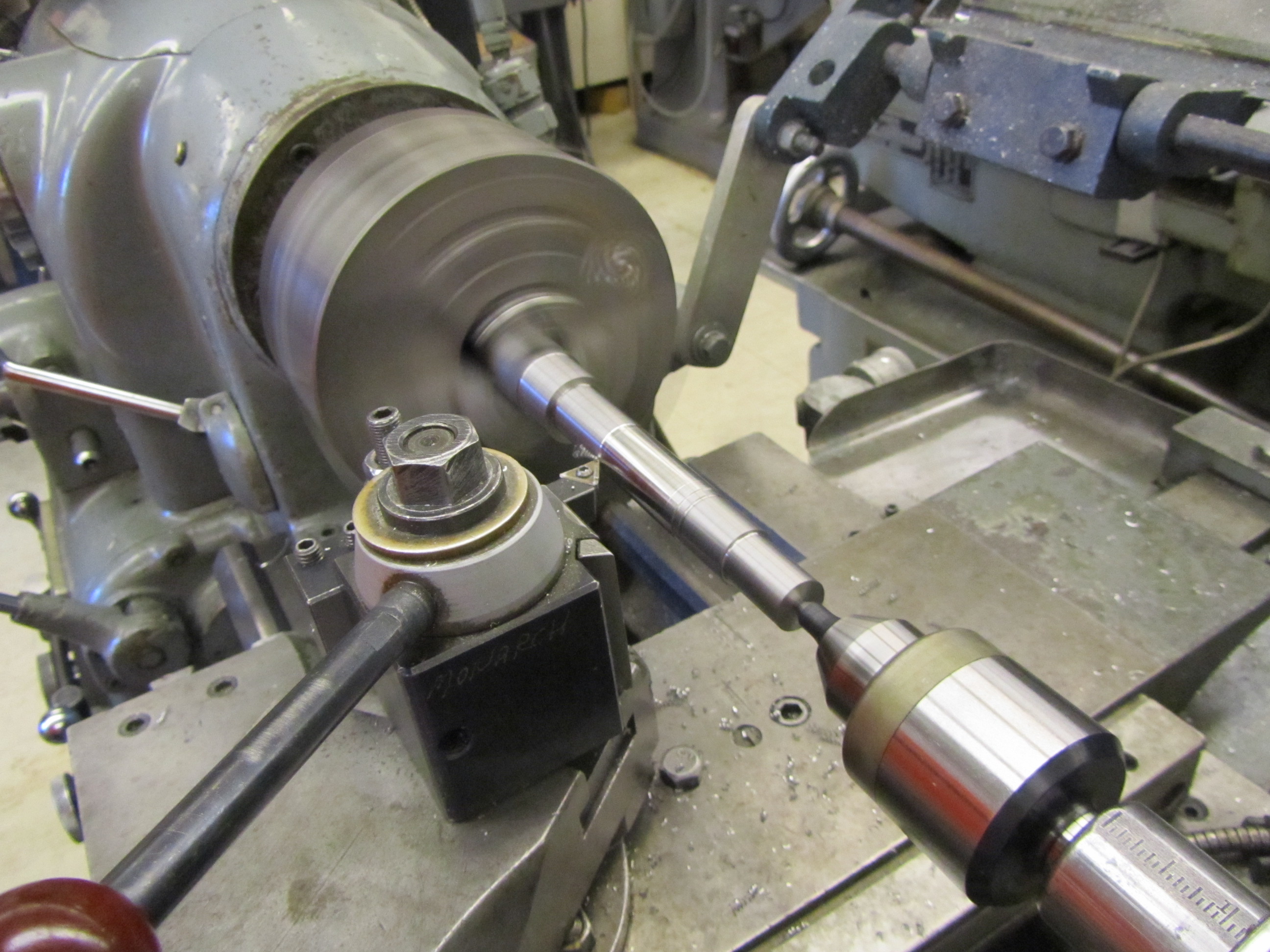 As you can imagine, manufacturing the spindle is also quite tricky. The drive shaft has several stepped diameters and it is threaded on both ends. To make matters worse, it is made of steel, which can generally take longer to machine and be less forgiving than aluminum. On average, machining the drive shaft takes about 8 hours. We machined our drive shaft and housing mostly in the Edgerton Student Shop, but there was some work that was done in the Hobby Shop, Pappalardo, and LMP.
 The Cross slide is an important part of the lathe, as it provides the X-axis for the tool.
The significant contributions that our group added was adding a flexure barrier, a chip guard, and using a thin film of bearing grease as a damper (although that last trick has been used by groups in the past).
 The leadscrew is an essential component of the lathe, as it provides the Z-axis for the tool. The leadscrew assembly has an arrangement of bushings, thrust bearings, preload nuts and most interestingly the “Dancing Man” flexure. The Dancing Man flexure is a 4 DOF flexure that relieves over-constraint caused by mounting the leadscrew nut to the carriage. The synthesis and explanation of the Dancing Man flexure is given in a Precision Engineering paper by Jon Hopkins and Martin Culpepper.
 The assembly is the entire lathe put together. Some important aspects to keep in mind are order of operations and bolt tightness. The tightness of the various nuts on the lathe affects the preload and therefore the performance (e.g. runout, heat generated, stiffness) of various components. The belt tensioner on the motor mount is driven by a double-ended screw. The thrust bearings in the leadscrew assembly are preloaded by nuts, as well as the thrust bearings on the cross-slide flexure. The cross-slide flexure itself is bolted to the carriage, and care must be taken to ensure that the bolts are tight enough to avoid hysteresis caused by micro-slip.
 The final competition was to remove a large chunk of material in the least amount of time. The entire chunk had to go through the shear zone, meaning that we could not simply part the chunk off. We attempted to take off the whole chunk in one pass, which was working fine until the belt slipped, which slowed us down. We came in 2nd place with a time of 1 minute 12 seconds, and the 1st place team (who completed the task in two passes) finished with a time of 46 seconds.
Professor Culpepper puts the lathes through the "Death Test." to check that they work well. The death test is comprised of four parts. The first part is to run the tool into the part as hard and as fast as he can. If the part breaks or the tool breaks that's fine, but if the spindle breaks, then your grade suffers. The second part is to have a group member stand on the carraige and be wheeled around on the X and Z axes. The third part is to hit the spindle on and off-axis with a sledgehammer. Finally the lathe is dropped from about waist height to simulate a customer dropping it off a desk.