tl;dr
To give the 2.75 class a start on design, analysis, manufacturing, experimentation, and electronics, we had to make a Kinematic Coupling and an EKG.
Kinematic Coupling
DesignAnalysis
Manufacturing
Testing
Results
Design
 I wanted to make a kinematic coupling that was both unique and functional. I eventually decided to make the Kinematic Coupling that I needed for NanoInk. That way, I get the assignment done for 2.75 and I make more progress on NanoInk research. The plan was basically to make the Kinematic Coupling that Adrienne made for her Master's thesis, but as I was looking through some of her old files, I was able to find out why some features were made the way that they were. For instance, there used to be a hole and a slot that was in both halves of Adrienne's kinematic coupling. I think those were for machining fixtures, so I was able to just get rid of them for my kinematic coupling. The parts were made of stainless steel. They were magnetic, which was convenient because the parts were so small.
Analysis
 The analysis for the Kinematic Coupling was done first using the spreadsheet made by Professor Slocum, but then I decided that it was difficult to use because of the nomenclature he defined. I eventually used the spreadsheet made by Adrienne and Professor Culpepper. I found it much easier to use (one helpful feature was a diagram with a KC and the labeled variable names.) The spreadsheet calculated a stiffness of 7.4 N/micron.
Manufacturing
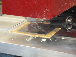 For such a small part, the manufacturing was quite interesting. I ended up using Mitee Grip clamping compound to hold down a the work piece to an aluminum plate. To use Mitee Grip, just place the workpiece on top and heat it up. A hot plate is recommended, but I used a heat gun because using the hot plate would take too long for the big aluminum piece that I put in the vise. I machined both halves of the kinematic coupling with a 1/16" endmill. To make the V-grooves, I used a 1/8" V-bit from Performance Micro Tool. I was happy that I could use small tools on hard parts and not break anything.
Testing
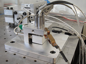 By far, the hardest part of this assignment was making the test setup for testing repeatability. The KC is so small that it's hard to attach any measurement device to it. Also, the parts are made of stainless steel, which means that the repeatability is probably going to be on the submicron level. To measure repeatability in all six degrees of freedom with a submicron resolution, I used six capacitance probes. The probes measure distance by correlating a change in distance to a change in capacitance. The resolution can be down to 0.3 nanometers. The kinematic coupling is still too small, so I made a big fat block to put on one half of the kinematic coupling that the cap probes could measure distance. The cap probes also needed a holder. For such a small, confined space, I decided to make a monolithic cap probe holder that used set screws with a nylon tip to hold each one in place. The monolithic design also ensured orthogonality amongst the cap probes to within the orthogonality of the mill used.
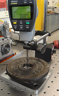 Testing stiffness was also a challenge. Testing stiffness in all six degrees of freedom would require several setups: three known forces would have to be applied in three orthogonal directions, and three known torques would have to be applied about those three orthogonal axes. Typically, the only important stiffness is the out of plane (z-direction) motion, so that is what I tested. In my lab, we have a dial indicator that has a resolution of one micron. To test stiffness, I applied a weight to the kinematic coupling target and measured the deflection. The actual stiffness turned out to be 0.74 N/micron.
Results