Explanation for Eddy's Method of Graphical Analysis
The methodology behind this graphical analysis for hemispherical masonry domes is based on the 1877 textbook New Constructions in Graphical Statics by Professor Henry T. Eddy at the University of Cincinnati.
Eddy's method assumes that internal hoop forces in the dome do not contribute to its structural stability. As a result, this method is conservative in determining parameters such as the minimum thickness-to-radius ratio of the dome because it simplifies the dome as a series of arches rotated about a common center.
After the user defines the geometric parameters of the dome, such as radius and thickness, the volume of each voussoir is determined by multiplying u, the arc length of each voussoir, by w, the mean width of each voussoir in plan, and the dome's thickness, t; each value is determined with geometry. This volume is multiplied by the material unit weight, giving the dead load of each voussoir, and added to the surcharge weight. The scale of the force polygon in units of kiloNewtons per centimeter on the screen is determined by the ratio of the total load-to-median radius of the dome.
Each voussoir has five forces acting on it: its self weight and loads, two meridional forces on its top and bottom surfaces, and lateral hoop forces from its neighboring voussoir.

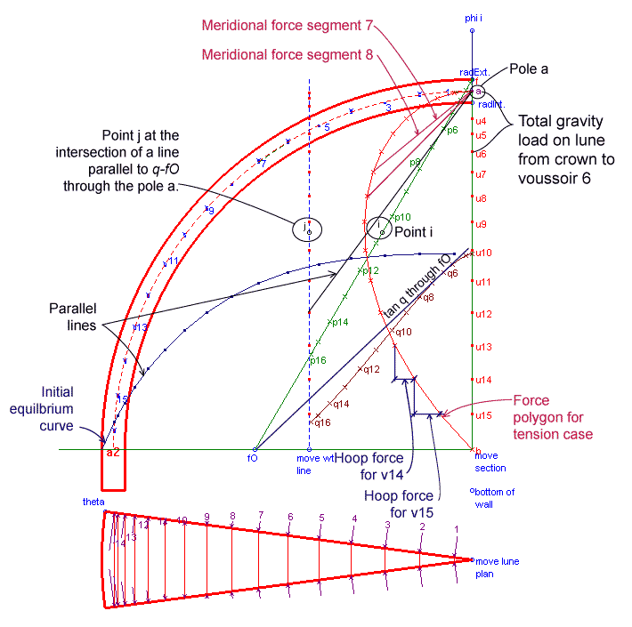
Gravity loads are represented on the vertical line ab. The portion of the total load on voussoir i is represented by the length of segment ui-u(i-1).
Meridional forces act in the longitudinal direction of a dome and increase from crown to base in magnitude. Meridional forces are due to the weight of the masonry and applied loads. Voussoir 8, for example, experiences meridional forces from voussoirs 1 through 7 above it, and also reaction forces from voussoirs 9 through 16 below. On the force polygon, the meridional forces on the voussoir's top and bottom faces are represented by the diagonal dashed vectors labeled "Meridional force 7" and "Meridional force 8," respectively. The mean length of these segments multiplied by the scale of the force polygon determines the average meridional force within the voussoir. The meridional force is then converted into a stress resultant with units of force per length. The length of the voussoir on which the meridional force acts is given by the mean voussoir width, w8.
Hoop forces act in a latitudinal direction of a dome on the lateral faces of the voussoirs, and contribute significantly to the stability of domes. For a dome with uniform axisymmetric loading, hoop forces from adjacent slices are equal in magnitude and act in the same plane. On the representative lune plan view, the hoop forces act in a direction perpendicular to the lune lateral faces. The horizontal components of the hoop forces on each side of a voussoir are equal and opposite. The resultant of two complementing hoop forces is a net force toward or away from the dome's center. The magnitude of this resultant equals the horizontal distance between two consecutive x-points.
The x-points occur at the intersection of a line parallel to the median radius through each voussoir through point "a" on the force polygon with a horizontal line through the "u" points. As a result, the magnitude of the hoop forces depend on the meridional force values in this method of analysis.
On the representative lune plan view, the hoop forces shown represent hoop force resultants with units of force per length. To find the magnitude of the hoop force, multiply the magnitude listed under the hoop force resultants by u, the arc length of each voussoir.
On curve ab, the hoop forces are in compression until the curvature becomes concave (negative Gaussian curvature), or as Eddy states, "the hoop compression will vanish at that level of the dome where the equilibrium curve, in departing from the crown, first becomes more nearly vertical than the tangent of the meridian section."
Limit state analysis assumes that masonry has limited or no ability to resist tension forces. Tension forces in the dome causes adjacent lunes to move apart and the dome base to splay. For the case of no allowable tension hoop forces , the hoop forces below the horizontal ray are assumed to equal zero. Subsequently, a different approach is taken.
Setting an arbitrary distance by the weight line to the pole a, an equilibrium curve is drawn from the outside edge of the dome base. The curve is composed of segments parallel to awi that intersect at vertical lines through each voussoir's center of gravity. To fit the equilibrium curve within the section, curves pp and qq are drawn. These curves are created by points that depend on the dome geometry and the initial equilibrium curve.
To find the appropriate distance of the wt line from the pole a, the segments comprising the equilibrium curve must be elongated by ratio. This ratio is equal to the ratio that the distance of the wt. line to the pole must be diminished.
Point j on the wt line is the intersection point of the line through pole a that is parallel to a tangent line to curve qq through the point fO. Point i is the intersection point of a horizontal line through j and line fO. When points i and j align, the tangent of curve qq through pole a is now line fO. The equilibrium curve is now scaled to fit within the dome section. The equilibrium curve represents the line of thrust through the dome assuming hoop forces do not contribute to the dome's stability.
Return to Applet.
Go to Tutorial.
Return to Analysis of Masonry Domes HomePage.