How to Use Eddy's Method to Analyze Masonry Domes
This tutorials provides instruction on using the online masonry dome analysis applet
based on the graphical method of Henry T. Eddy.
This method, described in New Constructions in Graphical Statics
by Henry T. Eddy (Eddy 1877), is similar to an analysis method for an arch.
The force polygons for each voussoir in the lune share a common pole, a,
from which meridional forces and the outward horizontal thrust at the dome's base are
calculated. This method provides an equilibrium solution or
curve assuming zero hoop forces in the dome; that is, the dome consists of a series of arches butt against each other. For a more detailed background on this graphical
analysis method, see the Methodology page.
Overview
This java applet was developed using Cabri
Geometry II software by Texas Instruments.
To learn more about Cabri,
visit www.cabri.com.
Three general rules to keep in mind when using this
applet:
-
"Ctrl" key (Windows) + mouse drag will shift the viewing
window.
-
In general, bright blue open-circle points are
parameters that the user can control.
-
To align the dark blue equilibrium curve within the
dome section, slide the pt "wt line" along the horizontal axis until point "j"
aligns with point "i" on line "fO."
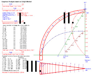
This tutorial will be divided into three parts as shown on the figure:
I. User-Defined Parameters
II.
Representative Dome Section and Force Polygon
III. Representative Lune in Plan.
I.
User-Defined Parameters
-
The four
sliding scales located on the left of the screen enable the user to define the structure to be analyzed and how its
force polygon will appear on the viewing screen. The minimum and maximum of
these values are shown and may not be modified.
- Dome Section Scale:
Adjusts the appearance of the representative dome section in terms of 1 cm on
the screen = n meters actual structure.
- Force Polygon Scale:
Adjusts the force polygon in terms of of 1 cm on the screen = n kiloNewton's
(kN) force.
- Material Unit Weight:
Specifies the unit weight (kN/m3) of the masonry. This will be treated as a uniform load on the dome. Uniform
live and snow loads and concentrated loads, etc., are considered as surcharge
weight in this applet, and should not be included here.
- Lune Plan Hoop Forces:
Adjusts the appearance of the hoop resultant forces on the plan view of the
individual dome lune.
-
Six geometric parameters in blue
text are located below the first two sliders.
- Exterior Radius: Slide the point "radExt." on the centerline of the representative dome section up
or down to specify the exterior radius of the dome. Note that the scales
may require additional refinement as other parameters are defined.
- Thickness: Slide the point "radInt" on the centerline of the dome section. This applet
assumes if the user knows the interior radius of the dome, then the thickness is known, and vice
versa. Note that thickness is in units of centimeters.
- Angle of Embrace:
The angle of embrace is fixed at 90 degrees, a hemispherical dome.
- Oculus Angle: Move the point "phi" on the dome section to modify the opening. The oculus
angle is the angle of the opening at the crown of the dome measured from the
crown. A dome with no oculus has a zero phi value.
- Theta: Move
the point "Theta" on the lune plan view to modify this value. Theta
represents the number of lunes into which the dome is approximated in plan view.
The maximum theta is 15 degrees, which is equivalent to dividing the dome into
24 wedges. Larger theta values reduce the accuracy of this analysis
method.
- Angle fO:
The angle of line fO with respect to the vertical axis is not critical.
However the point "fO" on the horizontal axis should be further left than the
blue "wt line." Line fO establishes the ratio at which the initial
equilibrium curve, c, is elongated to fit within the dome section.
-
Using the geometric parameters, the applet
returns the following parameters: the mean radius,
thickness-to-radius (t/R) ratio, and the Vouss. Arc Length, u.
-
Dead Load (kN): The
dead load is calculated automatically by the geometry of the dome as defined by
the user.
- Total Load (kN):
The total load represents the total load of the uniform and surcharge loads for
the individual lune. To find the total weight of the dome, multiply this
value by (360/theta).
- Surcharge (kN):
Surcharge values depend on the amount added by the user by dragging the
surcharge points down (see Note II.C. below).
- Voussoir Width
(m): The average width of each voussoir in plan view is calculated by the
geometry of the dome and lune as defined by the user.
- Force Polygon
Scale (kN/cm): The force polygon is forced to fit in the mean radius of
the dome, ab. The weight and applied loads and total load values
on this lune are scaled to fit proportionally by the force polygon scale.
II.
Representative Dome Section and Force Polygon
-
The dome
section is evenly divided into 16 voussoirs:
1. The u
value represents the arc length of one voussoir along the mean radius of the
dome, and is
constant for all voussoirs.
2.
The w value represents the mean width of each voussoir in plan, and
increases from crown to base.
-
The median radius is indicated by
the red arc in the section.
- To add surcharge on
a particular region of the dome, move the bright blue points downward.
Every other point is labeled with its voussoir number. The points are
located at the approximate center of gravity of each voussoir. Note
that this analysis assumes axis-symmetrical loading. Surcharge applied at
one location on this representative lune is assumed to occur in a ring
around the dome.
-
For clarity purposes, several lines
of the force polygons have been hidden.
-
Segment ab represents the
total load on this lune, including self weight and applied loads. Segment
u(i-1), ui represents the gravity loads on voussoir i.
-
The red cubic curve ab
connects the X-points for each voussoir's polygon in the case of existing
tensile resistance in the dome. For example, the triangle formed by
au5x, where x is the fifth x-point from the top represents the
equilibrium force polygon for the lune that includes the uppermost five
voussoirs. For a masonry dome with limited or no tension capability, this
curve is not applicable.
-
Wt line: The blue weight line
represents the force polygon for zero hoop force condition. To adjust its
location, slide the "Wt line" point along the horizontal axis to pinpoint its
final location with respect to the pole a.
-
Equilibrium curve c: The
equilibrium curve is the assumed line of thrust for this analysis method.
Its location can be adjusted by moving the weight line.
-
Line fO and pp: Move
the point "fO" along the horizontal axis so it is left of the wt line.
-
Curve qq: This curve
determines the elongation necessary of the equilibrium curve. The user
does not directly modify it. Note that this curve should fit under line fO
after the initial equilibrium curve is elongated.
-
Points j and i: Slide
the weight line along the horizontal axis until point j on "wt line" is
directly on point i on line "fO." Equilibrium curve "c" should now
fit within the dome section.
-
Move section: Move the point
"move section" to shift the dome section around the screen.
-
Bottom of wall: Move the blue
point "bottom of wall" to elongate the wall section, which acts only to enhance
the perspective of the dome section.
III.
Representative Lune in Plan
-
In the bottom left corner of the screen,
internal Resultant Forces (kN/m) values are calculated for each voussoir i
for the case in which tension forces are allowable.
1. Hoop values: to find the total hoop force of
a voussoir, multiply this value by u, the arc length of one voussoir.
-
Negative values indicate hoop forces
are in tension. Positive values indicate hoop forces are in compression.
-
Note that hoop forces are maximum
compression at the crown of the dome, decrease to near zero, and then become
tensile. This transition corresponds with the intersection of the hoop forces with
the lateral faces of the lune in plan view (see figure below).
2. Meridional values:
to find the total meridional force of a voussoir, multiply this value by wi,
the mean width of a voussoir.
-
Meridional forces are positive and in
compression. Meridional forces increase from the dome's crown to base.
-
Meridional force resultants listed
are the values at the center of gravity of the voussoir.
From the force polygon, the meridional force resultant of voussoir i is
given by the average length of the segments from point "a" to the i th
x-point and the (i-1)th x-point, which define the voussoir's top and bottom
faces.
3. Horizontal Thrust at Dome
Base: This value represents the outward horizontal thrust at the base
of the lune.
-
Representative Lune in Plan
-
Theta: Move point "theta" to
define the number of individual lunes into which the dome is divided.
-
Move lune plan: Slide
this point along the dome centerline to move the lune plan in the viewing
window.
Return to
applet.
Go to
Methodology.
Return to Analysis of Masonry Domes HomePage.