
INTRODUCTION
While
two-dimensional (2D) nanofabrication techniques, such as electron
beam and x-ray lithography, nanoimprinting, dip-pen lithography,
etc, can reliably produce features less than 20nm, these methods
lack the ability to create non-planar patterns, i.e. three-dimensional
(3D) structures. The use of the 3rd dimension will allow micro/nano-scale
devices to provide additional flexibility or even enable completely
new functions. The 3rd dimension also helps overcome the related
challenge of bridging the gap between the nanoscale features
of a system and the macroscale (Figure 1).
The Nanostructured Origami™ process overcomes this difficulty
of utilizing the 3rd dimension by borrowing ideas from the
Japanese art of paper folding, or origami. By first patterning
2D membranes via conventional lithography tools and then folding
them into an arbitrary layout, almost any 3D shape can be
formed. Of course, each of these folded membranes will have
been patterned in the previous step with the desired mechanical,
electrical, optical, and other functions (Figure 2 and 3).

Figure
1 Bridging the gap between nanoscale and macroscale.


(a)
(b) (c)
Figure 2 (a) Planar fabrication. (b) Membrane folding.
(c) Completed device.
CURRENT
PROGRESS
FOLDING
METHODS
We are currently investigating two main methods for origami-style
membrane folding: Lorentz force actuation and residual-stress
induced curling.
In
the Lorentz force actuation method, a current is applied to
a segment to be folded in the presence of a magnetic field.
By the Lorentz law, there will be an upward force acting on
the outer edge of the segment, as shown in Figure 4.
Another
folding scheme that we are investigating treats silicon nitride
as “paper.” Crease areas are first lithographically
defined, and folding is induced by depositing a stressed metal
layer on top of the nitride. We are able to fold the nitride
layer to an arbitrary angle by adjusting the size of the crease
and manipulating the residual stress of the deposited metal
actuation layer.
Figure
5 shows the scanning electron microscope (SEM) image of a
layer folded beyond 360o. The radius of curvature is approximately
20 microns, which is approximately the same as the radius
of a human hair.
Figure
6 shows an overhead view of curling. The upper layer is chrome
and looks white under the microscope. The underlayer, silicon
nitride, is a darker green color. One can observe folding
from the outer corners.

Figure 4: Membrane folding via Lorentz force

Figure 5: SEM image of 360o fold.

Figure 6: Overhead view of curling.
COMPLETED
DEVICES
Several devices have been successfully fabricated. Our first
devices were fabricated using silicon as the structural material
of the flaps and folded up to 180º using the aforementioned
Lorentz force actuation method. Gratings with sub-40nm features
were also incorporated into the fabricated devices. The next
generation of devices used a polymer called SU-8 as the structural
material. Figure 8 shows a two-flap device made of SU-8 that
has popped out of the substrate due to the stress-induced
folding scheme mentioned previously. Figure 9 shows pyramid
structures that are used for maintaining spacing and alignment
between different folded layers. Figure 10 shows the device
after the folding step is completed.

Figure 7: Gratings of nanoscale feature size integrated
into folding device

Figure 8: Two-flap device after partial folding induced
via residual stress.


(a)
(b)
Figure 9: (a) Origami using the SU-8 process. (b) Close-up
view of the alignment pyramids.

Figure 10: Overhead image of a two-flap device.
KINEMATIC
MODELING
Software
has been developed for visualizing the folding process and
modeling the kinematics of origami structures. Our model begins
by attaching a closed “skeleton” structure to
the origami segments. The skeleton is then broken into two
parts and forward kinematics are performed in the part that
contains the actuation mechanism. The second part is constrained
by the integrity condition, and so its motion is estimated
via inverse kinematics. Singularity in the inverse kinematics
of the second part indicates that kinematic integrity is violated
in the given structure. Kinematic compatibility is ensured
by tracking the segment edges (this function has not yet been
implemented in our software tool). The GUI of the developed
software is shown in Figure 10, and Figure 11 shows an example
of the visualization and kinematic modeling process [1].

Figure
11: Software developed for visualizing and doing kinematic
modeling the folding process.

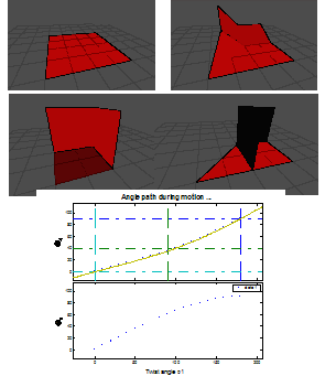
Figure 12: Five-segment origami mechanism (actuation sequence
shown clockwise on top) and the folding angles of two of the
segments in response to actuation of the diagonal joint.
CONCLUSION
AND FUTURE WORK
The
Nanostructured Origami™ Fabrication and Assembly Process
has been developed for 3D nanomanufacturing using conventional
2D lithography tools. Results presented above show great promise
for this technique, and we are already in the process of applying
this method to the fabrication of novel 3D nanostructured
devices, such as energy storage systems and multi-layer diffractive
optical elements.
REFERENCE:
1. T. Buchner, "Kinematics of 3D Folding Structures for Nanostructured Origami," Diploma Thesis, Laboratory for Machine Tools and Production Engineering, RWTH Aachen University (2004).
BACK TO TOP