Sensing for Control of URVs
Underwater robotic vehicles (URVs) need to employ a number of sensors that interact with the environment in order to measure various physical quantities (measurands) and to transfer the acquired information to the central processing system that processes the information and uses it to make decisions. URVs are space-constrained with low internal volume, energy-limited, and need to maintain neutral buoyancy. Given this stringent situation, the sensors developed must be small-sized with low foot-print, light in weight, robust, low-powered, surface-mountable while maintaining the streamlined body of the robot.
We developed two types of Microelectromechanical systems (MEMS) sensors that benefit the situational awareness and control of a robotic stingray by measuring various key control parameters responsible for the stingray locomotion. The first one is piezoresistive Liquid crystal polymer (LCP) flow sensor which are deployed to determine the steady velocity of propagation of the stingray. The second one is piezoelectric (PZT) micro diaphragm pressure sensors which are developed to measure the low-frequency oscillatory pressure stimuli generated by the stingray fins. Performances of the proposed PZT microdiaphragm sensors at very low frequencies (2 Hz and 1 Hz) are evaluated by performing digital holographic microscopy. The piezoelectric sensors demonstrate an excellent performance in tracking the trajectory of the fins of the stingray. These sensors also give information on the direction of propagation of the stingray and provide essential feedback on the fin flapping frequencies and amplitudes.

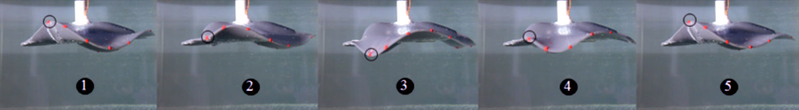
Figure 1. Piezoelectric MEMS sensors are employed to track the sinusoidal trajectory of the stingray fins (at the flapper location which is shown by circle in the figure) as the actuators are driven by a sinusoidal signal to generate 40º amplitude at a flapping frequency of 1 Hz. Top: The blue line shows the actual displacement of the fin of the stingray (at the flapper location) measured by taking images at various time throughout the flapping period using a high-speed camera. The red line shows the voltage output acquired from the piezoelectric sensor mounted on the stingray fin. Bottom: High-speed camera images at various time during the sinusoidal trajectory of the fin.