
|
|
|
| Thermodynamics and Propulsion | |
|
Next: 6.10 Muddiest Points on Up: 6. Applications of the Previous: 6.8 Some Overall Comments Contents Index
| |||||||||||||||||||||||||||||||||||||||||||
|
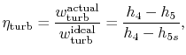
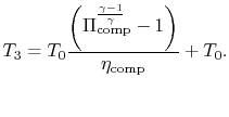
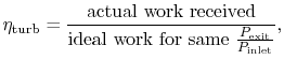
To develop a quantitative description of the effect of these departures from reversible behavior, consider a perfect gas with constant specific heats and neglect kinetic energy at the inlet and exit of the turbine and compressor. We define the turbine adiabatic efficiency as
 |
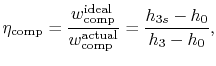
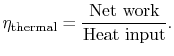
again for the same pressure ratio. Note that for the turbine the ratio is the actual work delivered divided by the ideal work, whereas for the compressor the ratio is the ideal work needed divided by the actual work required. These are not thermal efficiencies, but rather measures of the degree to which the compression and expansion approach the ideal processes.
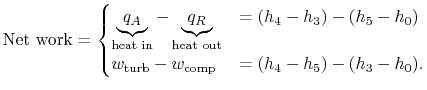
We now wish to find the net work done in the cycle and the efficiency. The net work is given either by the difference between the heat received and rejected or the work of the compressor and turbine, where the convention is that heat received is positive and heat rejected is negative and work done is positive and work absorbed is negative.
 |
We need to calculate
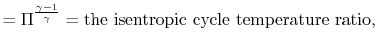
From the definition of
![]() ,
,
With
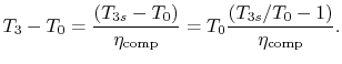
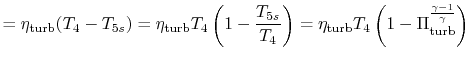
Similarly, by the definition
we can find
 |
||
 |
With
 |
||
|
and
| ||
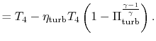
 |
||
![$\displaystyle = 1-\cfrac{T_4\left[1-\eta_\textrm{turb}\left(1-\cfrac{1}{\tau_s}...
...ht)\right]-T_0} {T_4-T_0\left[\cfrac{1}{\eta_\textrm{comp}}(\tau_s-1)+1\right]}$](img875.png) |
||
|
or
| ||
![$\displaystyle = \frac{\left[1-\cfrac{1}{\tau_s}\right]\left[\eta_\textrm{comp}\...
...0}-\tau_s\right]} {1+\eta_\textrm{comp}\left[\cfrac{T_4}{T_0}-1\right]-\tau_s}.$](img876.png) |
||
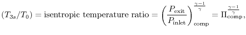
| : cycle pressure ratio | ||
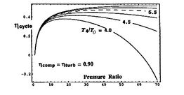
Putting this in a non-dimensional form,
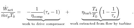
![$\displaystyle \frac{\dot{W}_\textrm{net}}{\dot{m}c_pT_0} =
(\tau_s-1)\left[\cfrac{\eta_\textrm{turb}\cfrac{T_4}{T_0}}{\tau_s}-\frac{1}{\eta_\textrm{comp}}\right]$](img887.png)
|
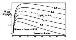
[Non-dimensional work as a function of cycle pressure ratio for
different values of turbine entry temperature divided by compressor
entry temperature]
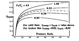
 [Overall cycle efficiency as a function of pressure ratio for
different values of turbine entry temperature divided by compressor
entry temperature]
[Overall cycle efficiency as a function of pressure ratio for
different values of turbine entry temperature divided by compressor
entry temperature]
 [Overall cycle efficiency as a function of cycle pressure
ratio for different component efficiencies]
[Overall cycle efficiency as a function of cycle pressure
ratio for different component efficiencies]
|
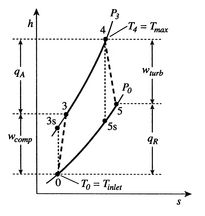
Trends in net power and efficiency are shown in Figure 6.17 for parameters typical of advanced civil engines. Some points to note in the figure:
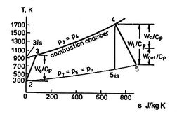
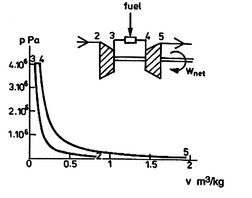
A scale diagram of a Brayton cycle with non-ideal compressor and
turbine behaviors, in terms of temperature-entropy (![]() -
-![]() ) and
pressure-volume (
) and
pressure-volume (![]() -
-![]() ) coordinates is given below as
Figure 6.18.
) coordinates is given below as
Figure 6.18.
|
[]
 []
[]
|
Muddy Points
Isn't it possible for the mixing of two gases to go from the final state to the initial state? If you have two gases in a box, they should eventually separate by density, right? (MP 6.22)
How can ![]() be the maximum turbine inlet temperature?
(MP 6.23)
be the maximum turbine inlet temperature?
(MP 6.23)
When there are losses in the turbine that shift the expansion in
![]() -
-![]() diagram to the right, does this mean there is more work than
ideal since the area is greater? (MP 6.24)
diagram to the right, does this mean there is more work than
ideal since the area is greater? (MP 6.24)
For an afterburning engine, why must the nozzle throat area increase if the temperature of the fluid is increased? (MP 6.25)
Why doesn't the pressure in the afterburner go up if heat is added? (MP 6.26)
Why is the flow in the nozzle choked? (MP 6.27)
What's the point of having a throat if it creates a retarding force? (MP 6.28)
Why isn't the stagnation temperature conserved in this steady flow? (MP 6.29)